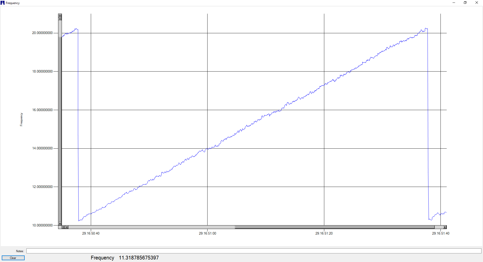
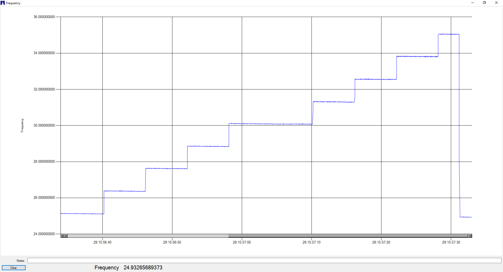
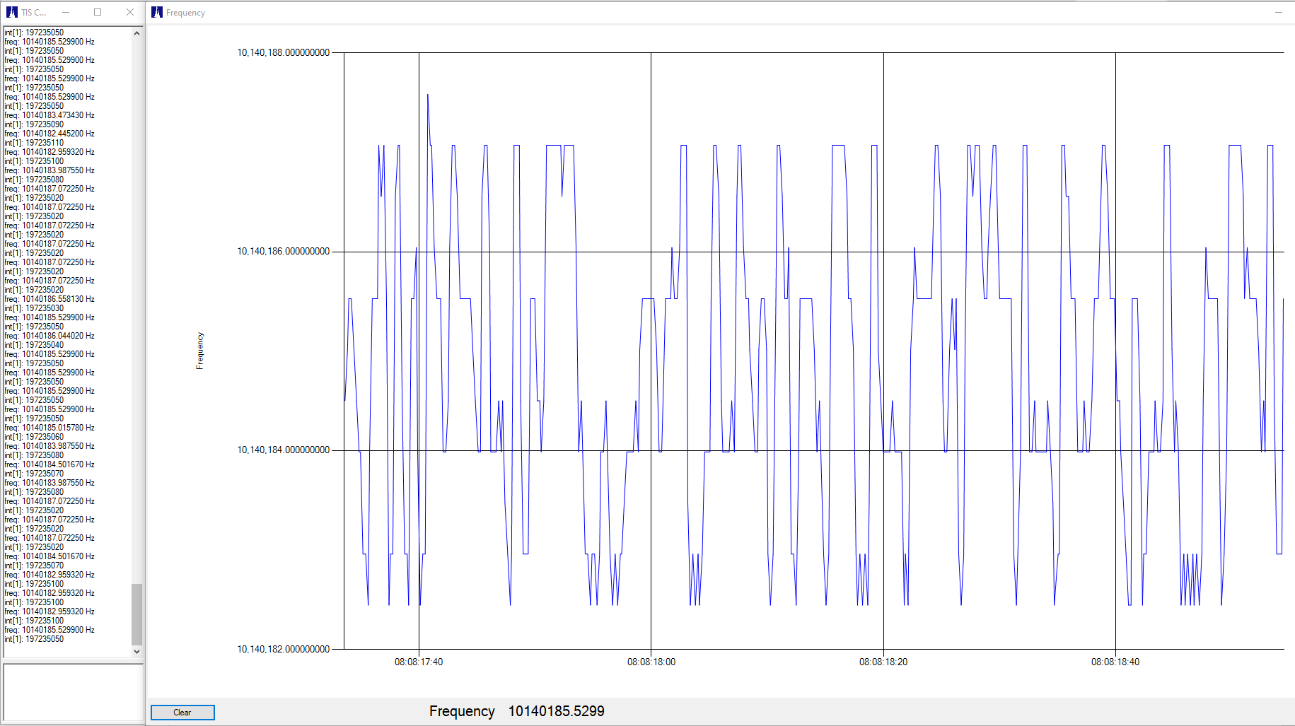
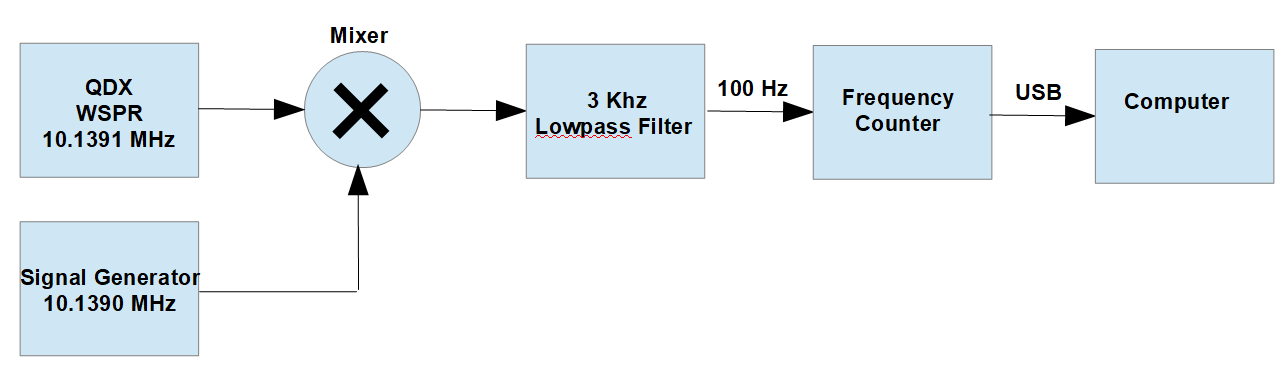
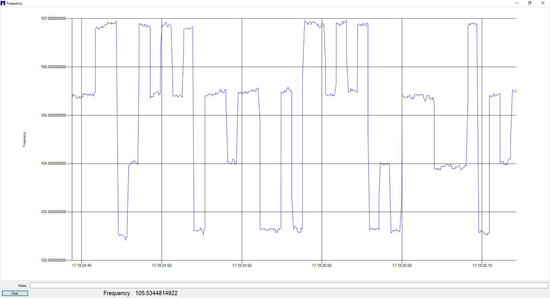
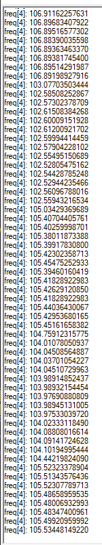
As has been mentioned before, the transmit frequency stability of the QRP Labs QDX transceiver isn’t quite good enough for some of the narrow-band modes. It works fine for WSPR and FT8, but slower modes such as FST4W-300, -900, and -1800 require stability that the QDX’s internal TCXO just can’t provide. Here is a plot of a FST4W-1800 transmission, showing the frequency drift as the QDX heats up during the long 30-minute transmit cycle:
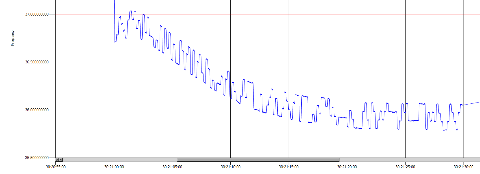
In the plot above, the actual transmit frequency is about 10 MHz, but my measurement system has mixed it down to about 36 Hz in order to get higher measurement resolution. Add 10.1402 MHz to frequency values shown on the plot. We can see that the transmit frequency initially rises by about +0.1 Hz, then eventually falls to -0.85 Hz.
FST4W-1800 has a FSK tone spacing of 0.089 Hz and does not track slow frequency drift, and so requires much better transmit stability than this. And remember, this test was done in the 10 MHz (30-meter) ham band, the drift will be double that at 20 MHz, and half that at 5 MHz.
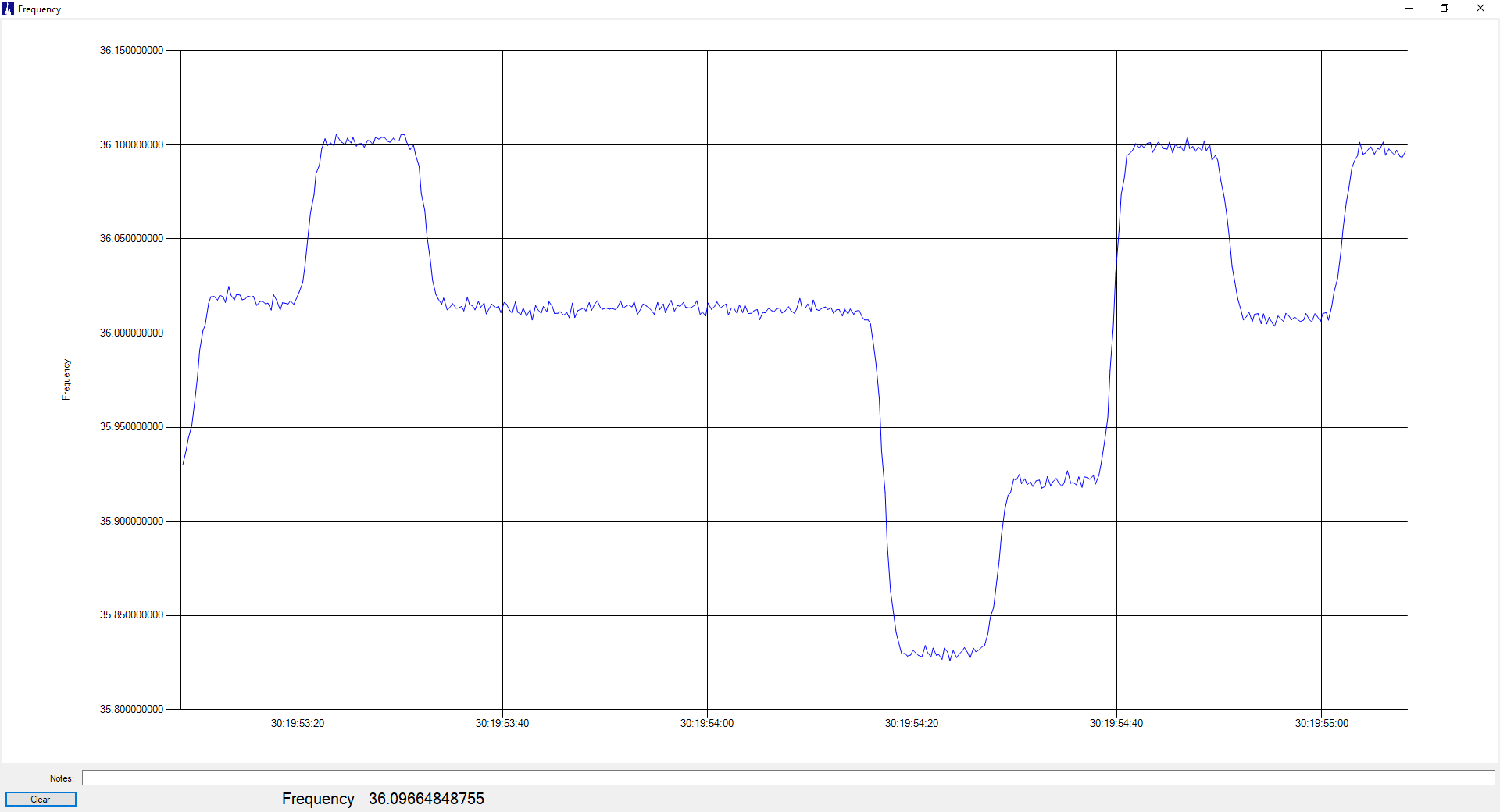
I spent some time looking at the causes and possible solutions for this drift. First, I ruled out any software issues by measuring the output of the QDX internal 25 MHz TCXO. Here’s a plot of the TXCO frequency vs ambient temperature, using a homebrew temperature chamber (the QDX was not transmitting during this test):
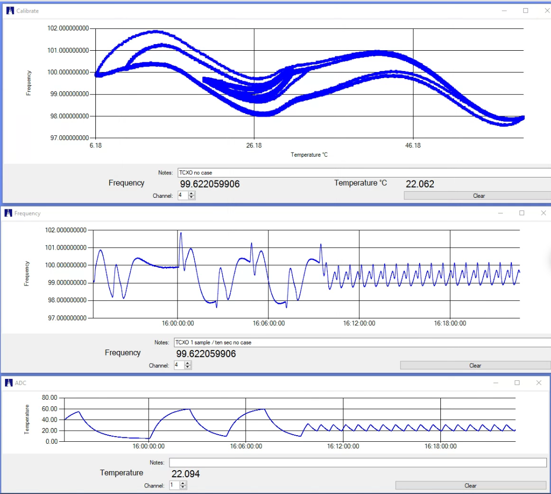
The top chart is frequency vs temperature, the middle one is frequency vs time, and the lower one is chamber temperature over time. Again, here my measurement system is shifting the 25 MHz TCXO frequency down to 100 Hz in order to obtain higher resolution. We can see that over a 6C to 60C temperature range the TCXO shifts over a range of 4.3 Hz.
We can also see the intriguing phenomenon of “retrace”, where the oscillator frequency exhibits a kind of thermal hysteresis. All crystal oscillators exhibit this behavior to some extent, and this does limit the amount of correction that can be performed by measuring the temperature (one of the options contemplated for the QDX).
I attempted to slow the rate of frequency change by increasing the thermal mass of the TCXO (attaching a brass tab to the TCXO package), but the results were disappointing — the TCXO is too solidly attached to the circuit board and the heat transferred though the board from the QDX output transistors just couldn’t be escaped.
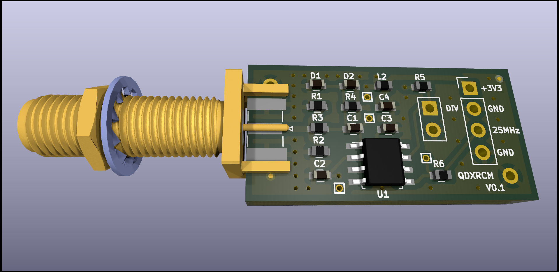
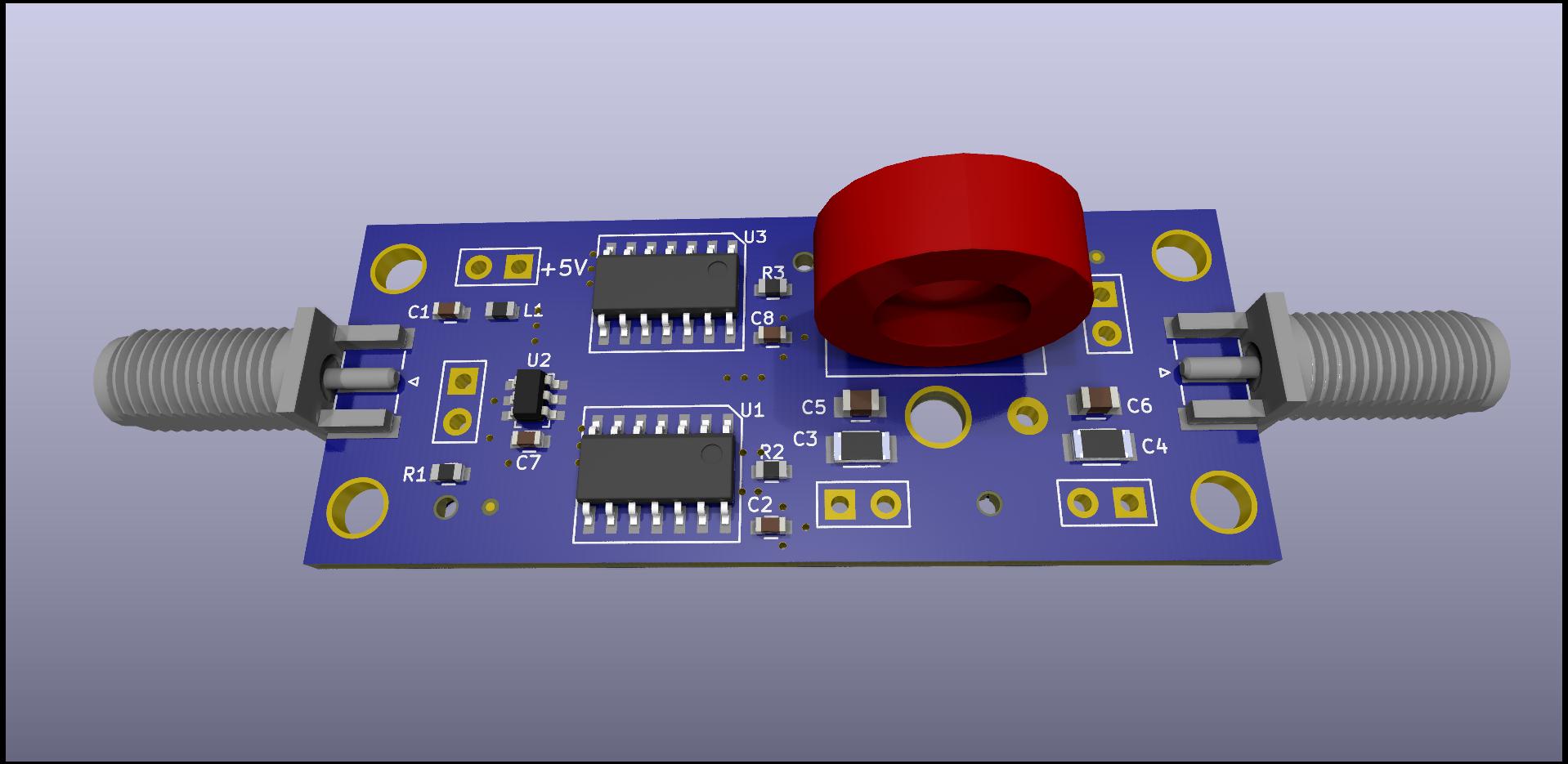
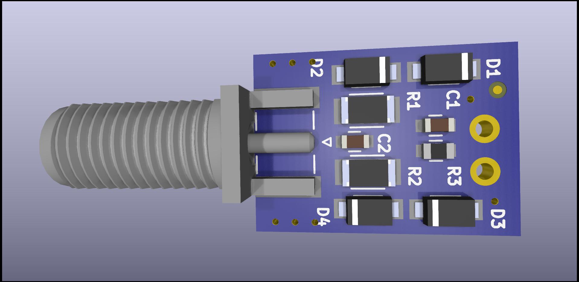
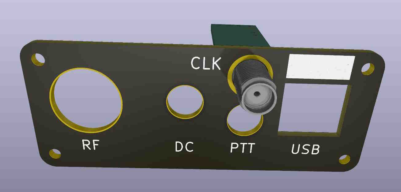
Setting aside any idea of a simple fix, I decided to bypass the TCXO entirely and provide an external clock. There was room (barely) on the rear QDX faceplate for a SMA jack, and room inside for a small circuit board, do I designed and built a little reference clock multiplier:
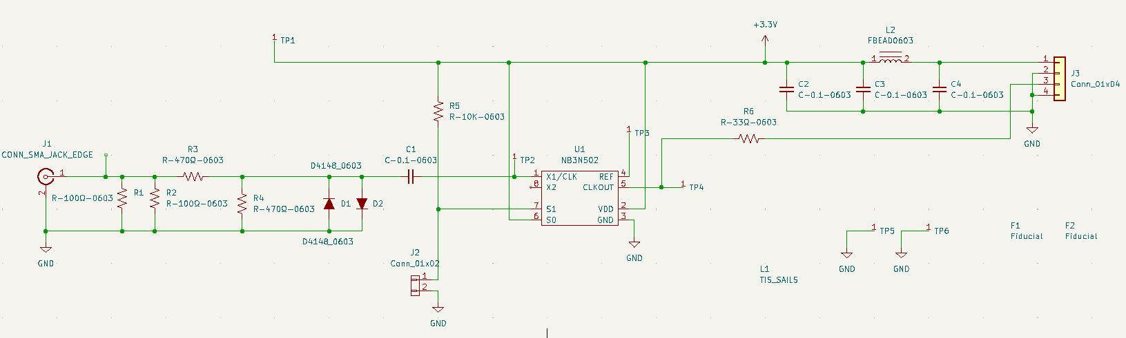
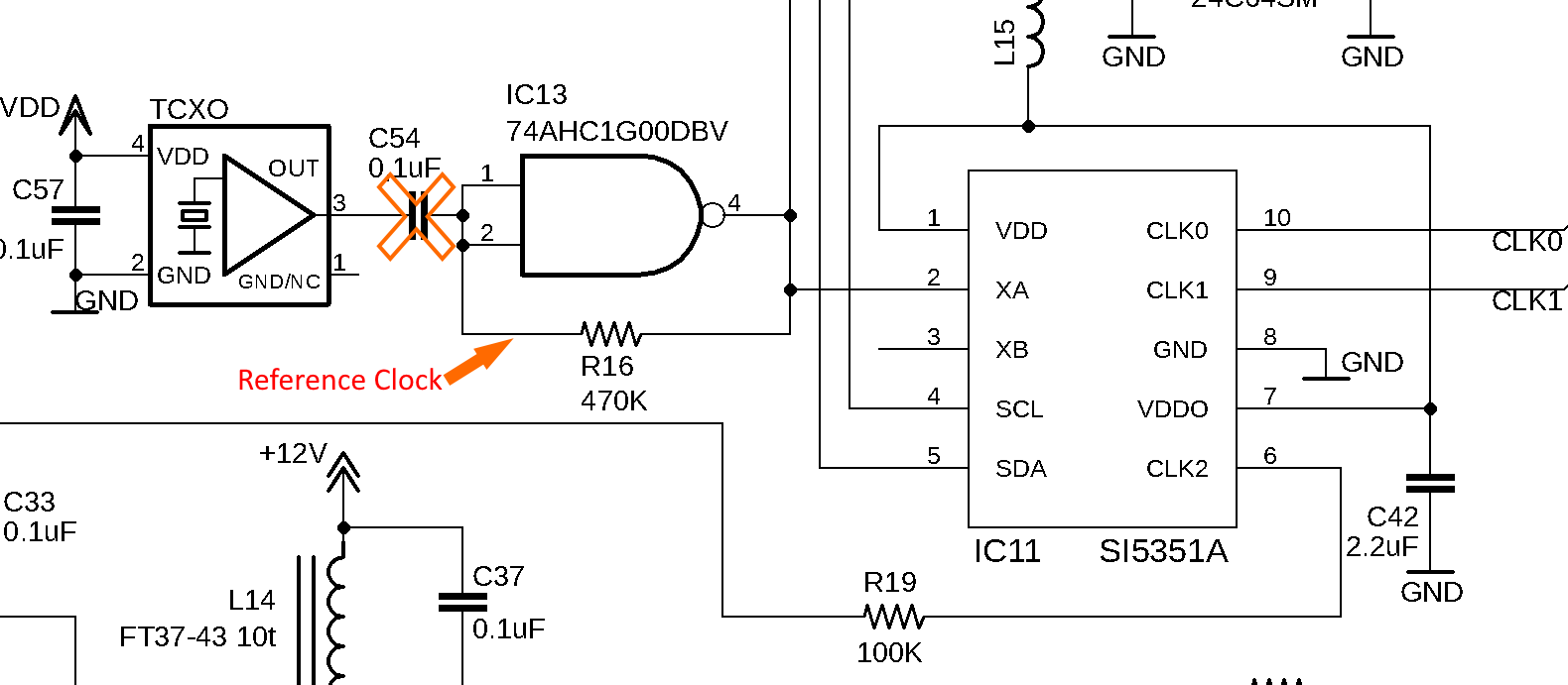
This simple circuit uses a PLL chip to multiply an external reference clock (either 5 or 10 MHz) up to the 25 MHz needed by the QDX. I will dig into more circuit detail in a later post. This circuit is powered by the QDX internal 3.3V supply, and provides a 0/3.3V logic-level output which is connected to the QDX clock buffer input (after removing the TCXO coupling capacitor):
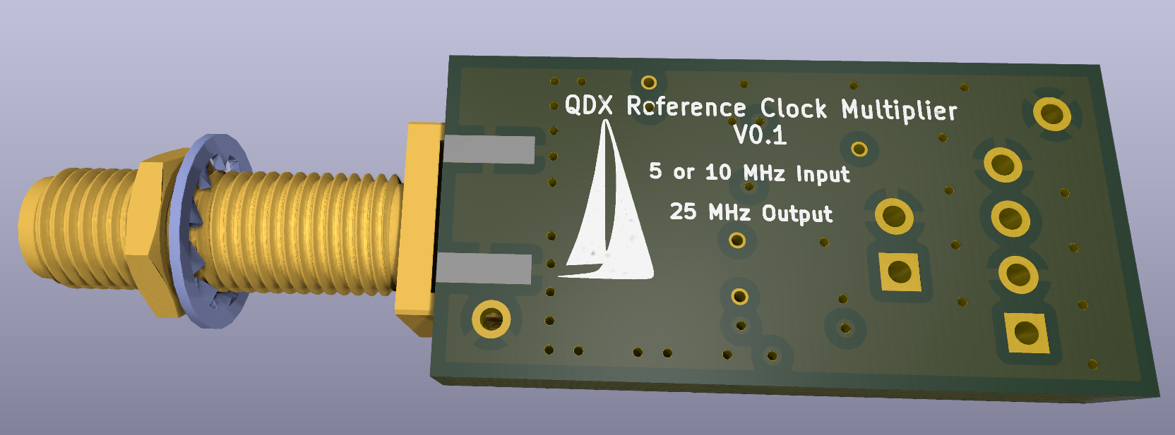
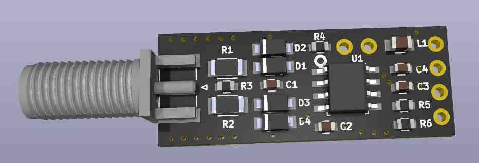
Here’s the little board layout:
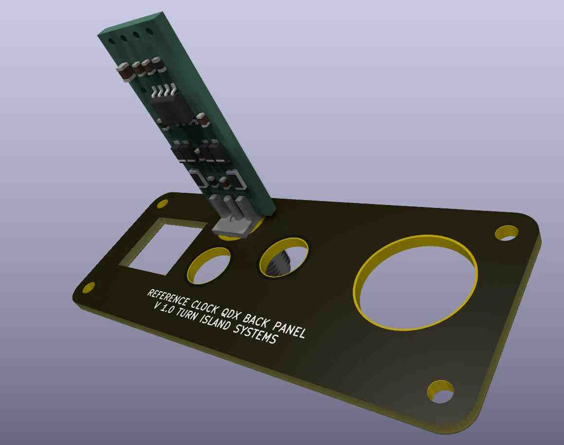
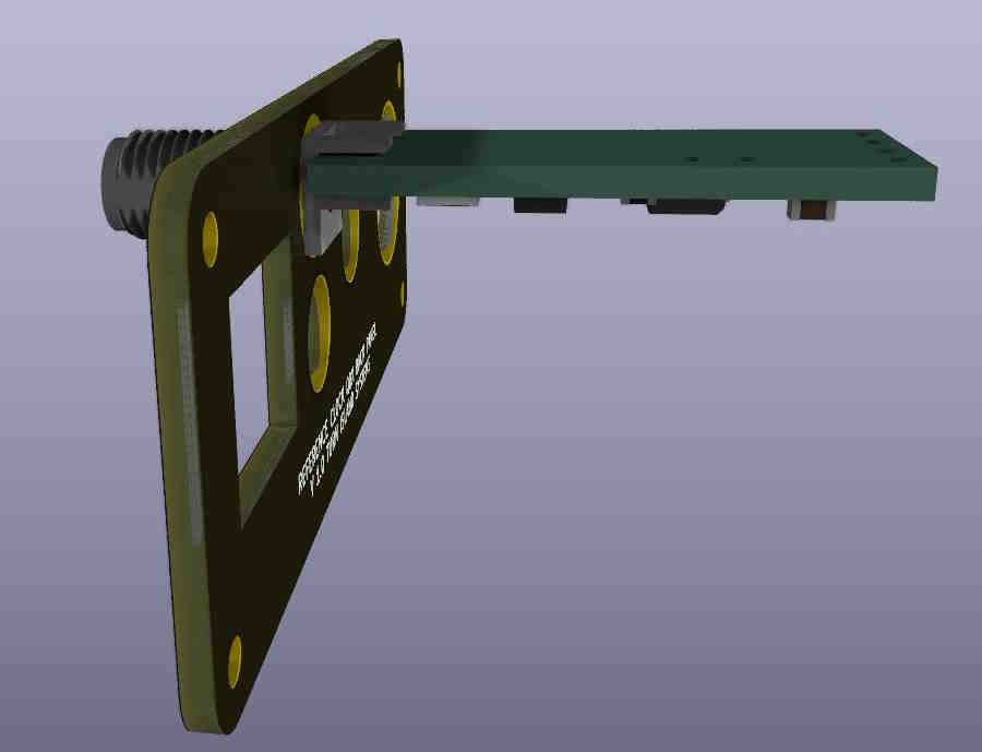
And as installed in the QDX:
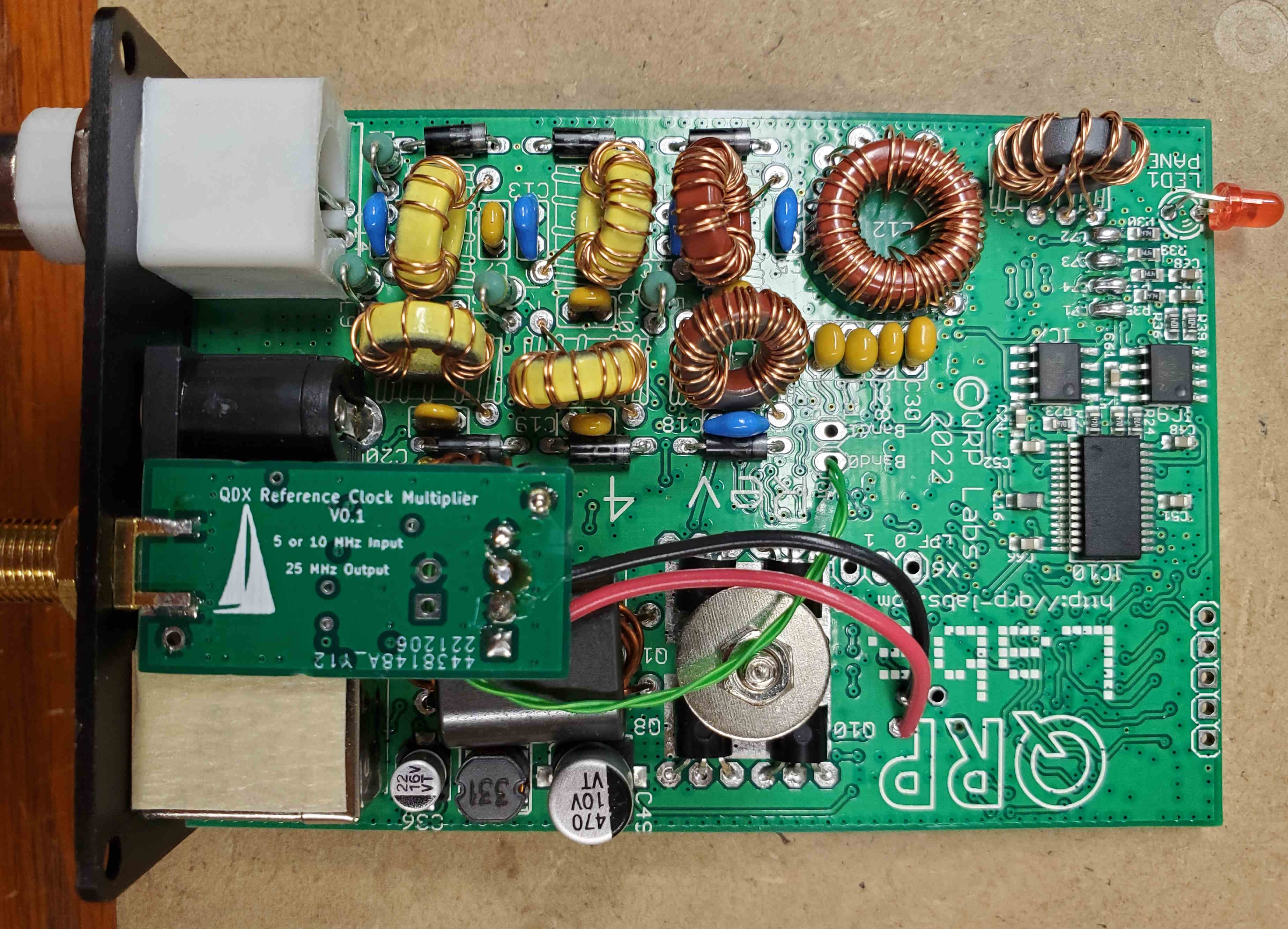
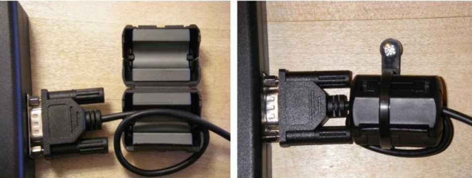
I picked up +3.3V and ground from some testpoints on the QDX board, and having no microscopic coax, I used a twisted pair of #30 Kynar-insulated wirewrap-wire to connect the clock signal to the QDX board (two different-color wires would have made more sense, but I was in a hurry). The twisted pair just managed to squeeze through another testpoint through-hole, and was then soldered to the PCB:
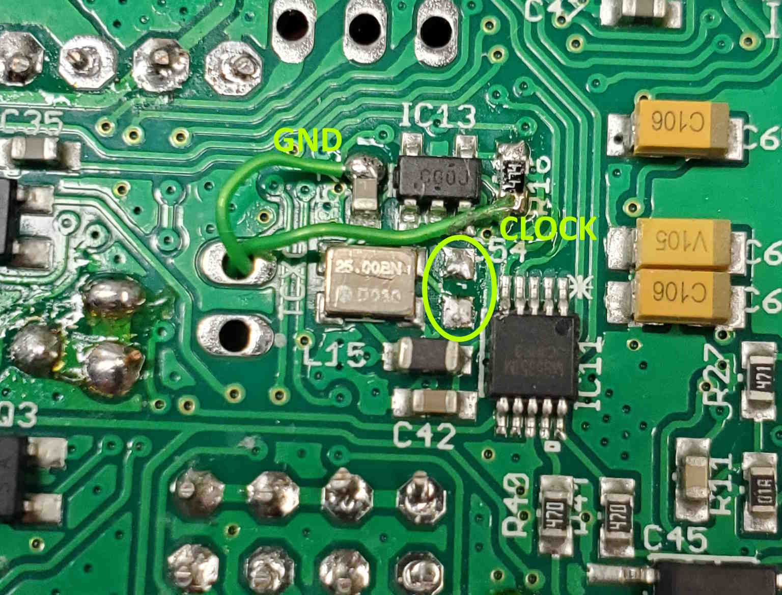
The yellow oval shows where the TCXO coupling cap (C 54) used to be.
Using a Bodnar GPSDO as my 10 MHz reference I ran some tests. The 25 MHz output from my PLL was reasonably clean, as was the resulting signal from the QDX. Here are some plots of the transmitter, in the 20-meter band:
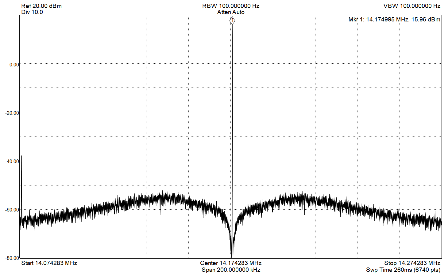
This is a 200 KHz span, 100 Hz resolution bandwidth scan, showing a bit of broadband noise and a discrete spur at -100 KHz (there is another near +100 KHz, not visible in this plot). This noise potentially affects the receiver performance, but initial measurements lead me to believe that other QDX noise sources are dominant. These measurements only show us the transmit signal, and to determine how much of this output noise is due to the PLL will require further testing. In any case, this noise will have no significant impact on the transmit performance. We can see how the noise falls off dramatically as we approach the carrier frequency — this is the characteristic of PLL noise under the loop-bandwidth frequency. Here is a close-in plot:
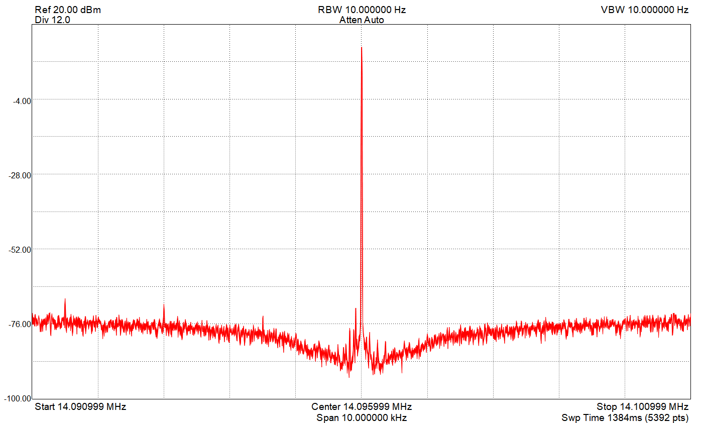
This level of noise is definitely acceptable.
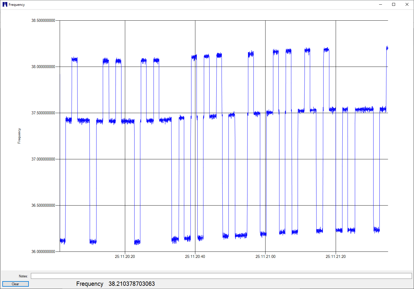
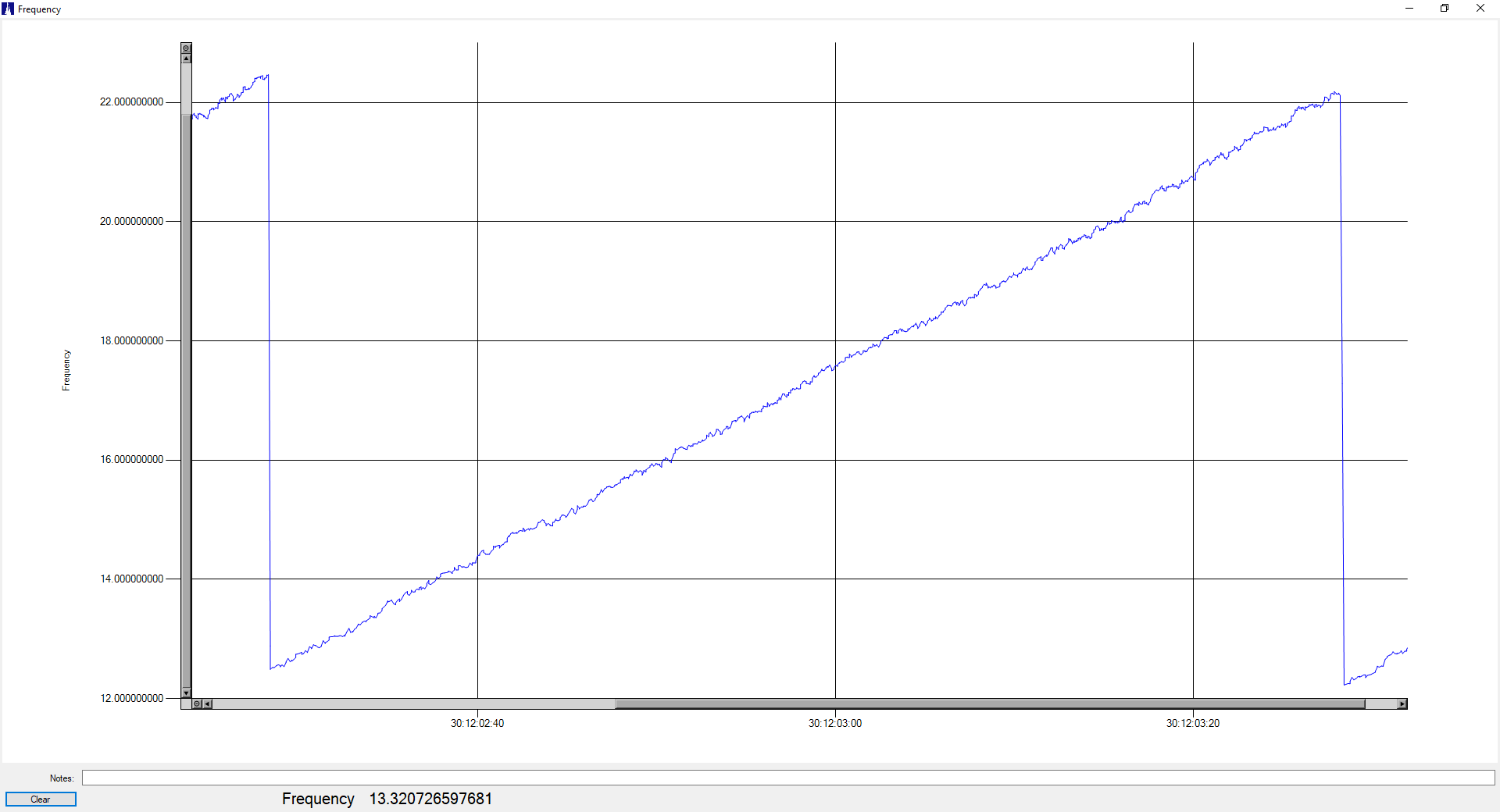
And here are plots showing the transmitted FST4W-120 signal, transmitting on 14.09715 MHz:
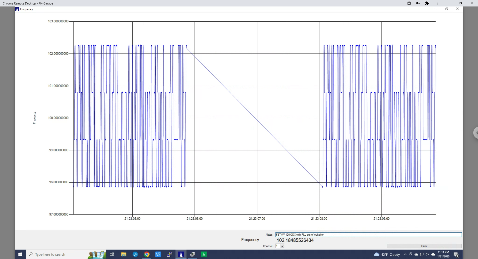
As expected, the transmit frequency is rock-solid. And here is the modulation in FST4W-1800 mode:
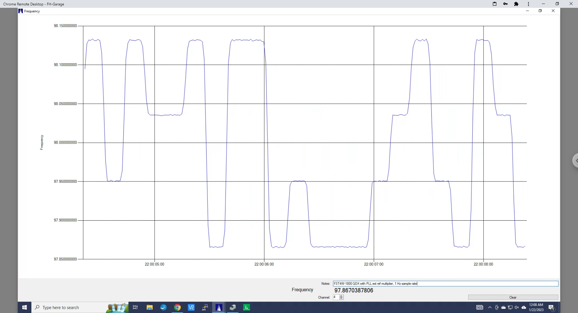
On-the-air tests of the modified QDX, transmitting FST4W-120 show essentially perfect performance.
About the external reference:
The reference multiplier input can come from any stable source of 5 or 10 MHz. I tested using a GPSDO, since I distribute that reference to much of my test equipment, but a stand-alone OCXO, or even stable TCXO will serve the purpose. Obviously, if you already have a stable 25 MHz clock available (the Bodnar GPSDOs can be configured to provide this) you don’t need a clock multiplier — just a connection to the QDX circuit board. Be sure to provide appropriate coupling and some type of input transient protection!
The 25 MHz clock not only drives the radio portion of the QDX, it also runs the microcontroller. Without this clock the QDX will not run, and any interruption will likely cause bad things to happen. The external clock source is the first thing I connect, and the last thing I disconnect.
 (Ignore those power-level numbers, I had a bad coax jumper)
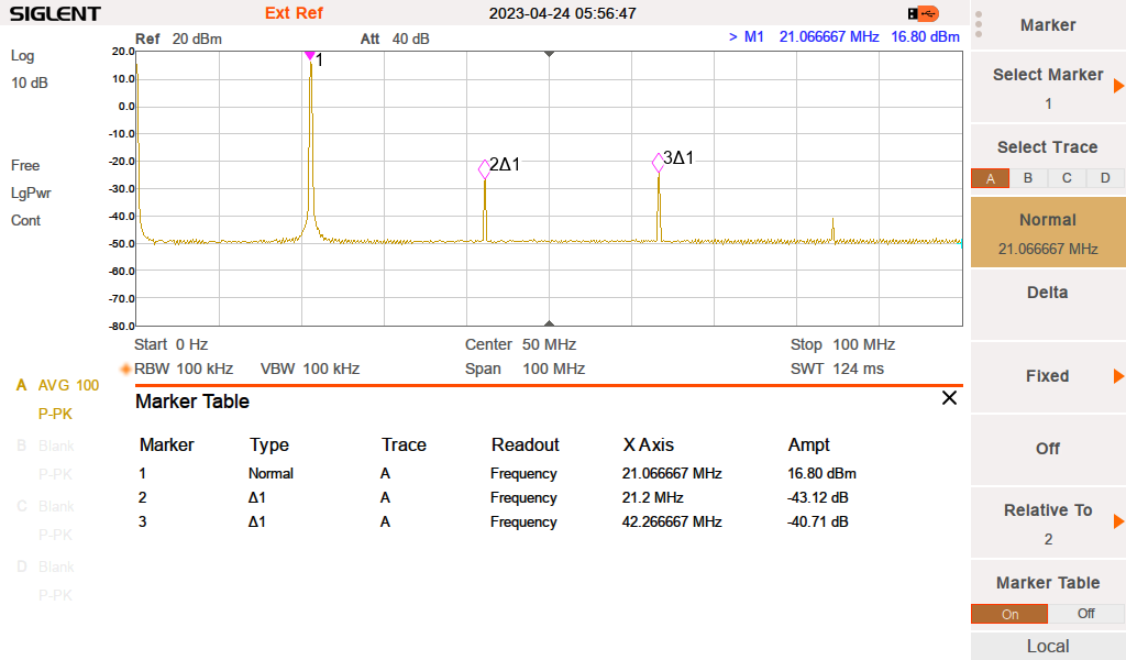
 Direct Interface Board
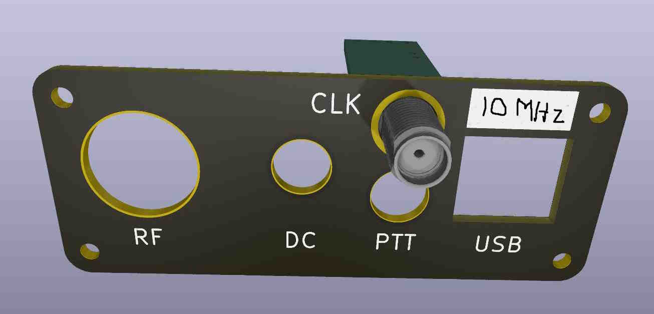