Many SDR receivers, especially those designed for full HF-spectrum use, have needed various filters and preamps between the antenna and the SDR. High-power AM and FM broadcast stations can overload the receiver front-end, so these are filtered out. The characteristics of atmospheric background noise are such that a “shelf” (or “shelving”) filter which attenuates the lower-frequency range can also be useful in optimizing the SDR dynamic range.
Finally, the SDR sensitivity / input noise-floor at the higher end of the spectrum can be marginal. Add the inherent losses of all these filters and a low-noise, high dynamic-range preamp becomes very useful.
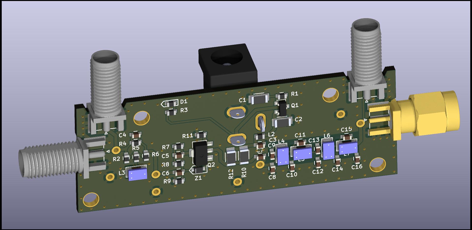
So I am designing the “Swiss Army Knife” of SDR front-end modules: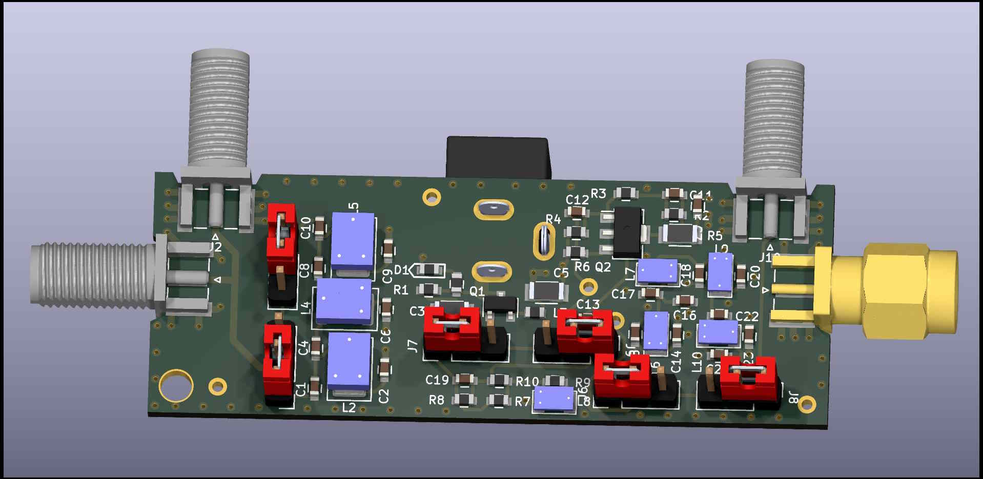
No, there aren’t four SMA connectors, only one pair will be installed, giving an “in-line” version, and a “right-angle” version that can fit on a small die-cast enclosure. There are four sections to this board:
- AM Broadcast Band filter
- 15dB Shelf filter
- 13db gain preamplifier
- FM Broadcast Band filter
Each of the filters can be bypassed using pin headers and jumpers. The amplifier components can be omitted during assembly and a jumper used to bypass this section.
The FM band filter allows for 6-meter reception, but many SDR receivers are clocked at 66 MHz or so, and require a lower corner frequency on the low-pass filter. This filter can optionally be built with a corner frequency at 30 MHz.
Amplifier:
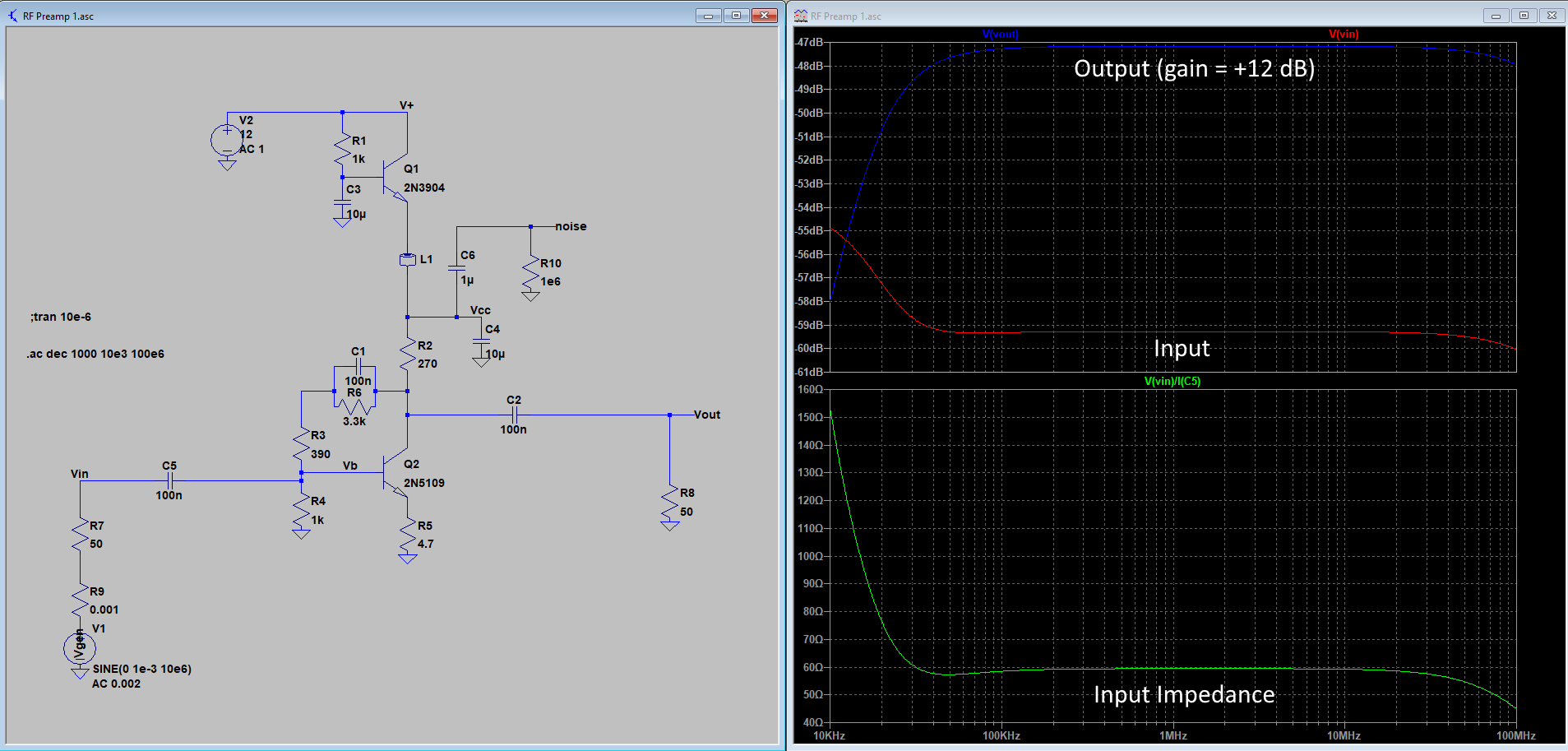
Amplifier simulated with 2N5109
The amplifier is a simple wide-band zero-inductor design (found in the November 1984 edition of Ham Radio magazine, page 100: https://www.worldradiohistory.com/Archive-DX/Ham%20Radio/80s/Ham-Radio-198411.pdf). It’s become difficult to find the classic 2N5109 transistor, so I am using the more modern BFU90Q, which has similar performance. But I am simulating with the 2N5109 because that’s the model I could find.
The amplifier draws about 20 mA from a +12V power source, and my board includes a simple but effective filter that eliminates most noise and ripple on the DC source.
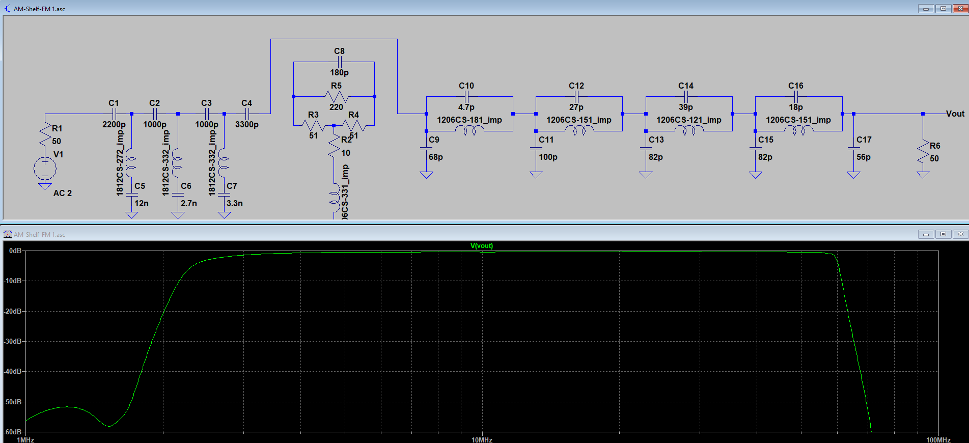
Here are the three filter sections:
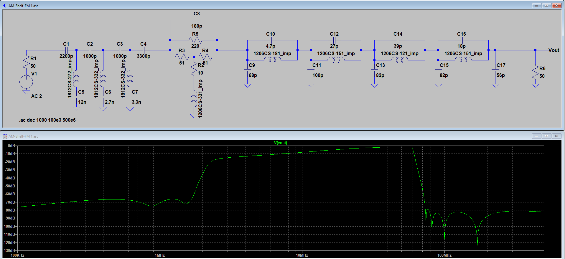
From left to right the first filter is the AM broadcast filter,. This starts attenuating below 3 MHz, and is at least -50dB down at the top of the AM band.
Next is the 15 dB shelving filter. In a previous filter I had two 10 dB shelf filters in series, with each of them bypassable. This limited-size board requires a compromise, so there is just a single filter section. The inclusion of the AM BCB filter should mitigate the effects of the simpler shelf filter configuration.
The right-hand filter is a elliptic low-pass design, that cuts off at 60 MHz. The attenuation in the FM broadcast band, and above, is approximately 80 dB. This is also an excellent anti-aliasing filter for the SDR.
With the shelf filter bypassed the filter response from 3 to 60 MHz is essentially flat:
With all filters and amplifier enabled, the overall gain at 60 MHz is about +10 dB. The input (blue trace) is -60 dBm, and the output (green trace) is -50dBm :
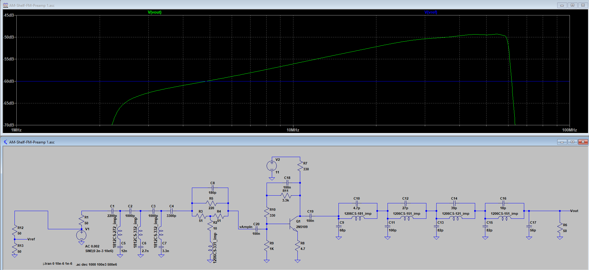
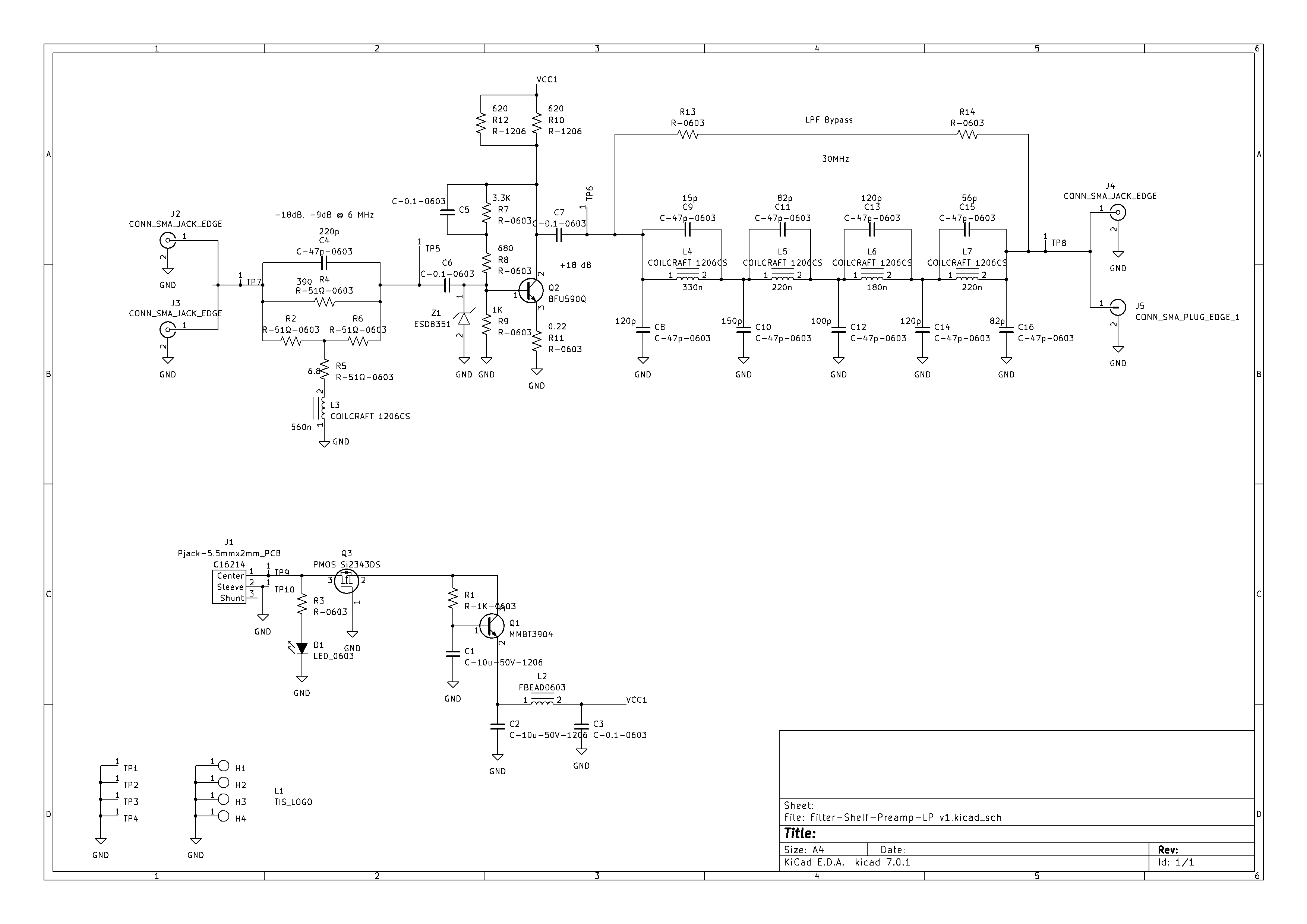
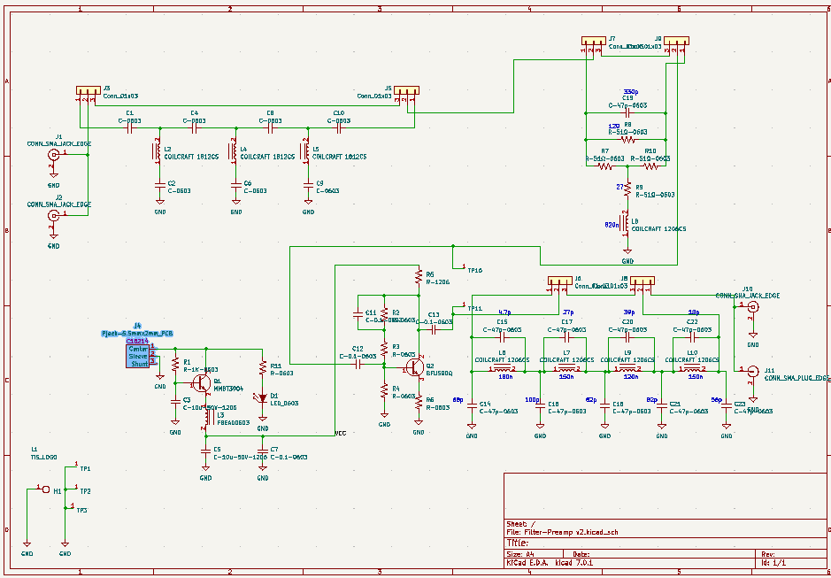
And here is the schematic for the whole thing:
 The simulated performance shown above should be reasonably close to the actual thing. At these frequencies the inductors are the largest source of simulation errors, but I am using Coilcraft inductors and their provided simulation models. These have proven to be remarkably accurate in previous designs.
But this is a tight little board, and layout parasitics may be an issue. You will see that the (unshielded solenoid) inductors have been oriented to reduce coupling, and (which you can’t see) the ground planes have been relieved underneath the most sensitive tuned circuits. I do hope that the amplifier won’t turn into an oscillator, but the design and layout do give me some optimism. I plan to have a working prototype in about a month.
Like the Swiss Army Knife, this design may not be the best tool for every job, but it should be useful in SDR receiver systems.
Acknowledgement: I would like to thank Clint Turner / KA7OEI for his invaluable advice on filters, amplifiers, and optimizing SDR performance. His excellent blog: https://ka7oei.blogspot.com/2020/08/revisiting-limited-attenuation-high.html
 And the schematic: