I’ve been busy. Here is the latest batch of designs that have been sent out for fab. Some are simple, some more complicated, and some are updates of earlier designs. KiCad and JLCPCB sure make this stuff easy!
Look for these designs to show up on the Turn Island Systems website.
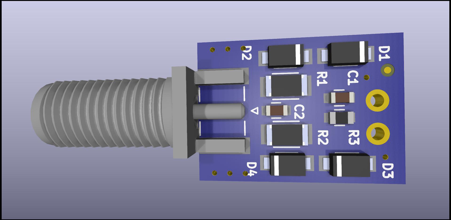
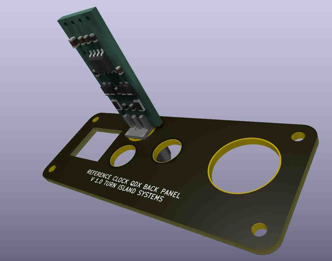
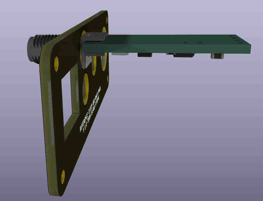
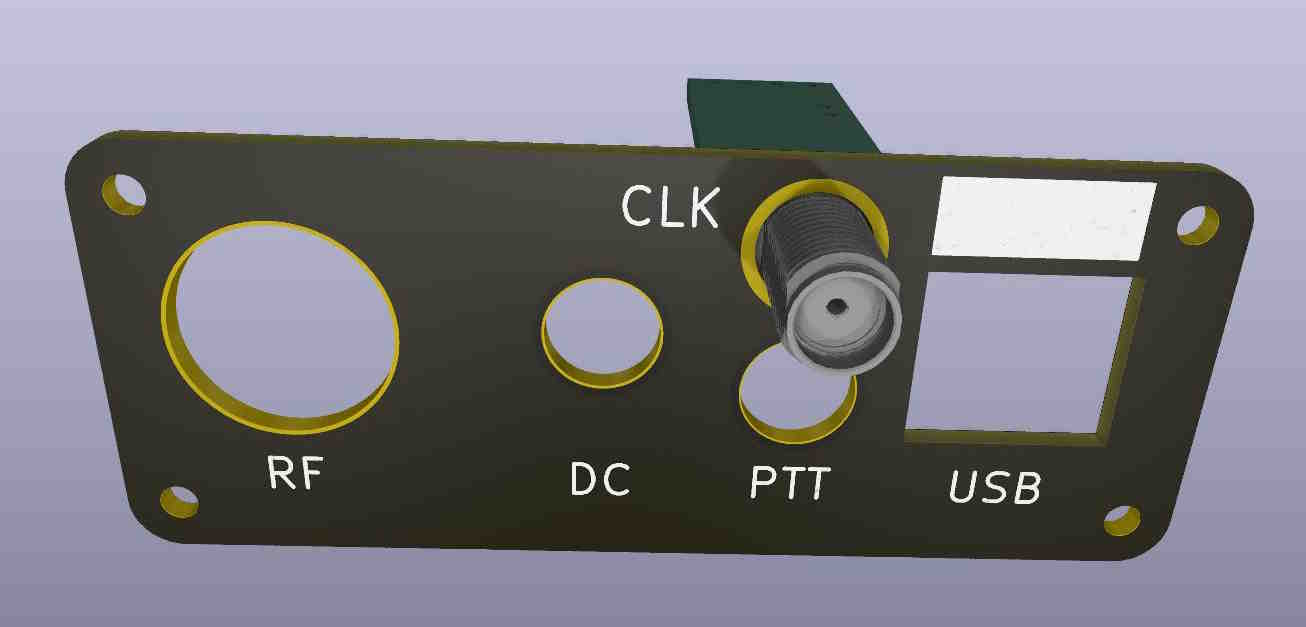
RX-888 External Clock Interface Kit:
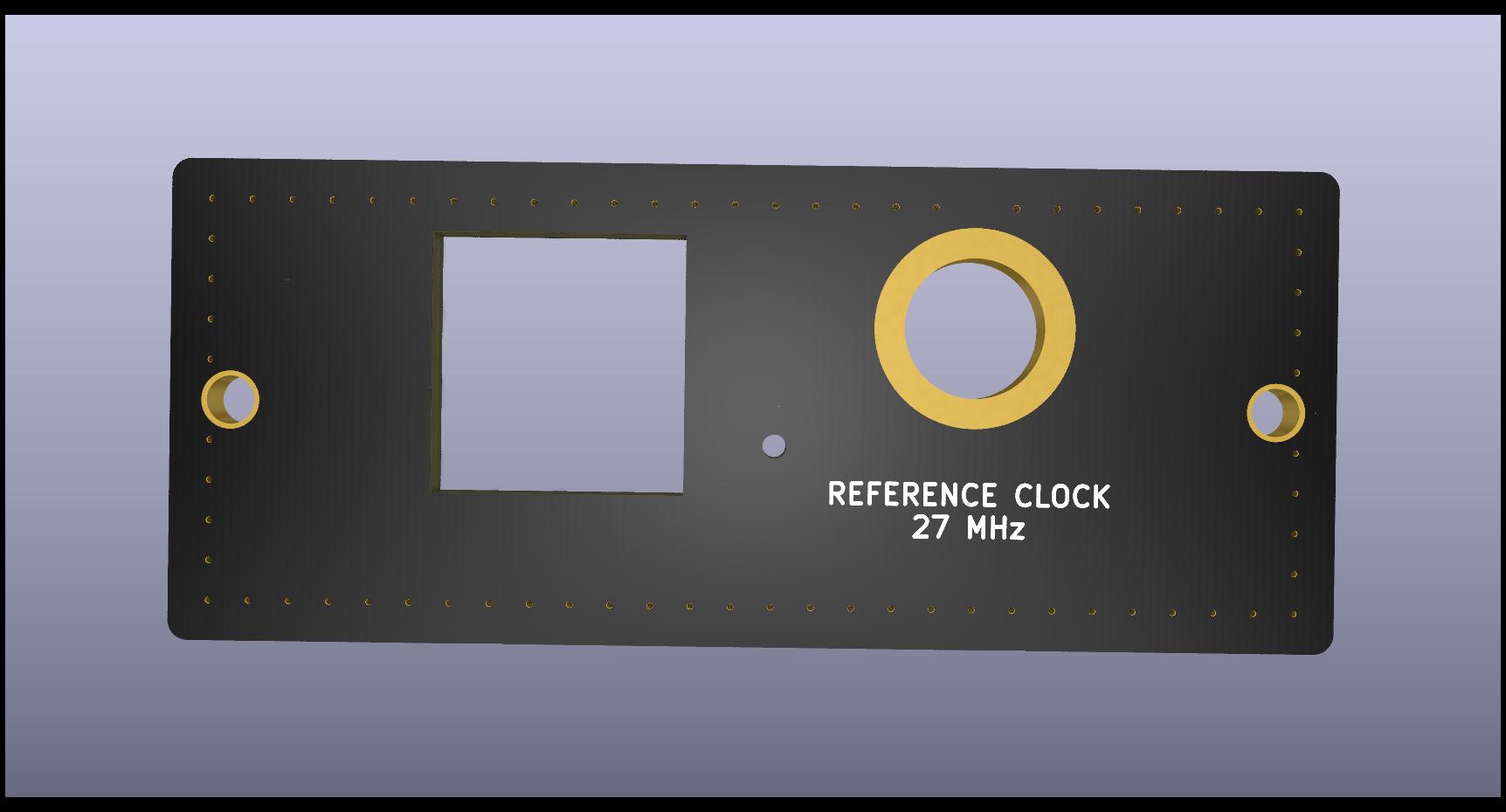
This is a fairly simple kit that provides termination, appropriate attenuation, and DC isolation for the external clock interface to the RX888 SDR. This includes the interface card, and a replacement back-panel for the RX888. The complete kit will also include a short U.FL jumper cable and a piece of thermal foam gasket that is used to reduce the RX888 internal temperature rise.
That SMA plug shown on the right side of the board is not present when this board is installed inside the RX888, but can be soldered on when the board is used externally.
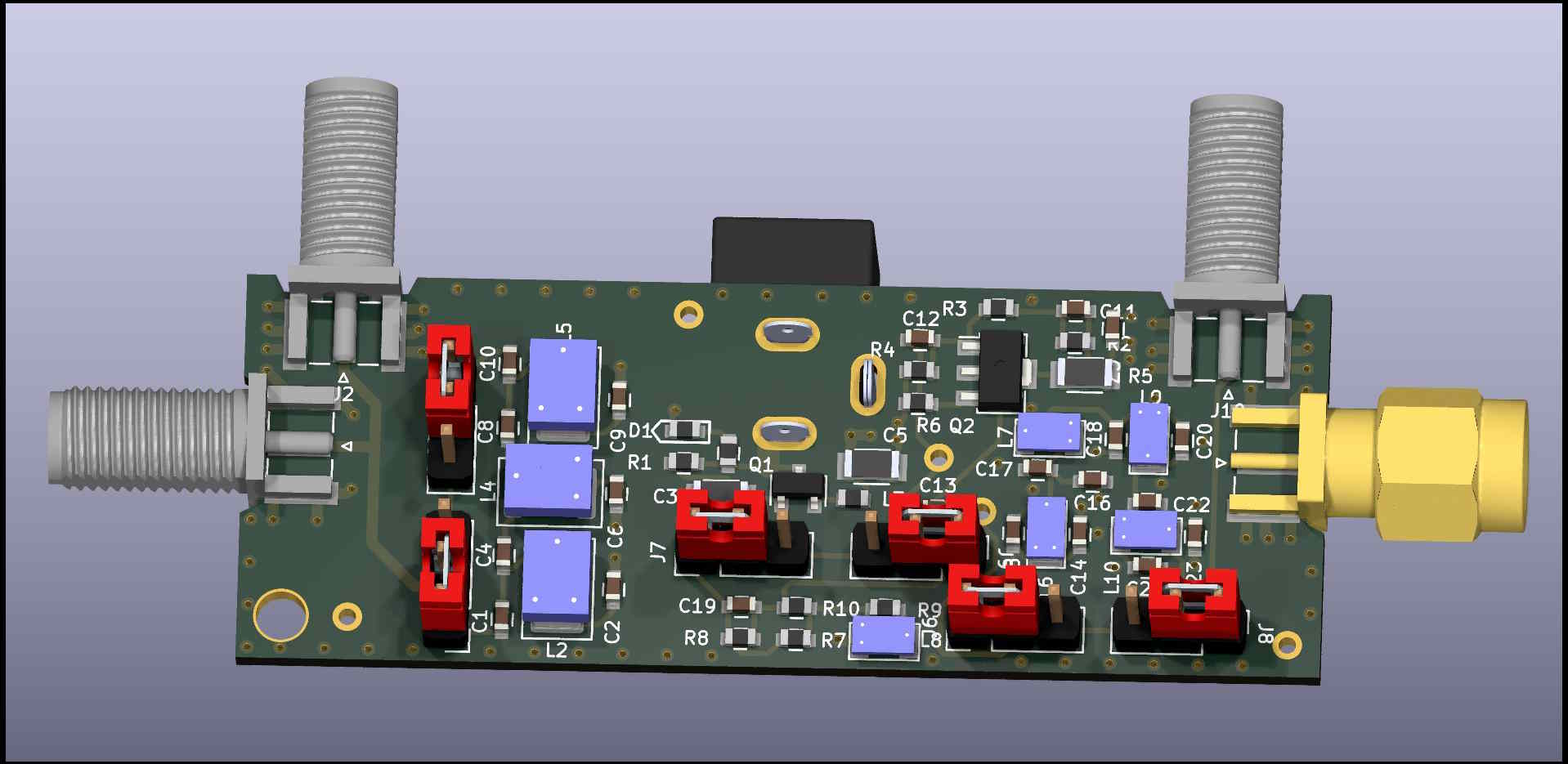
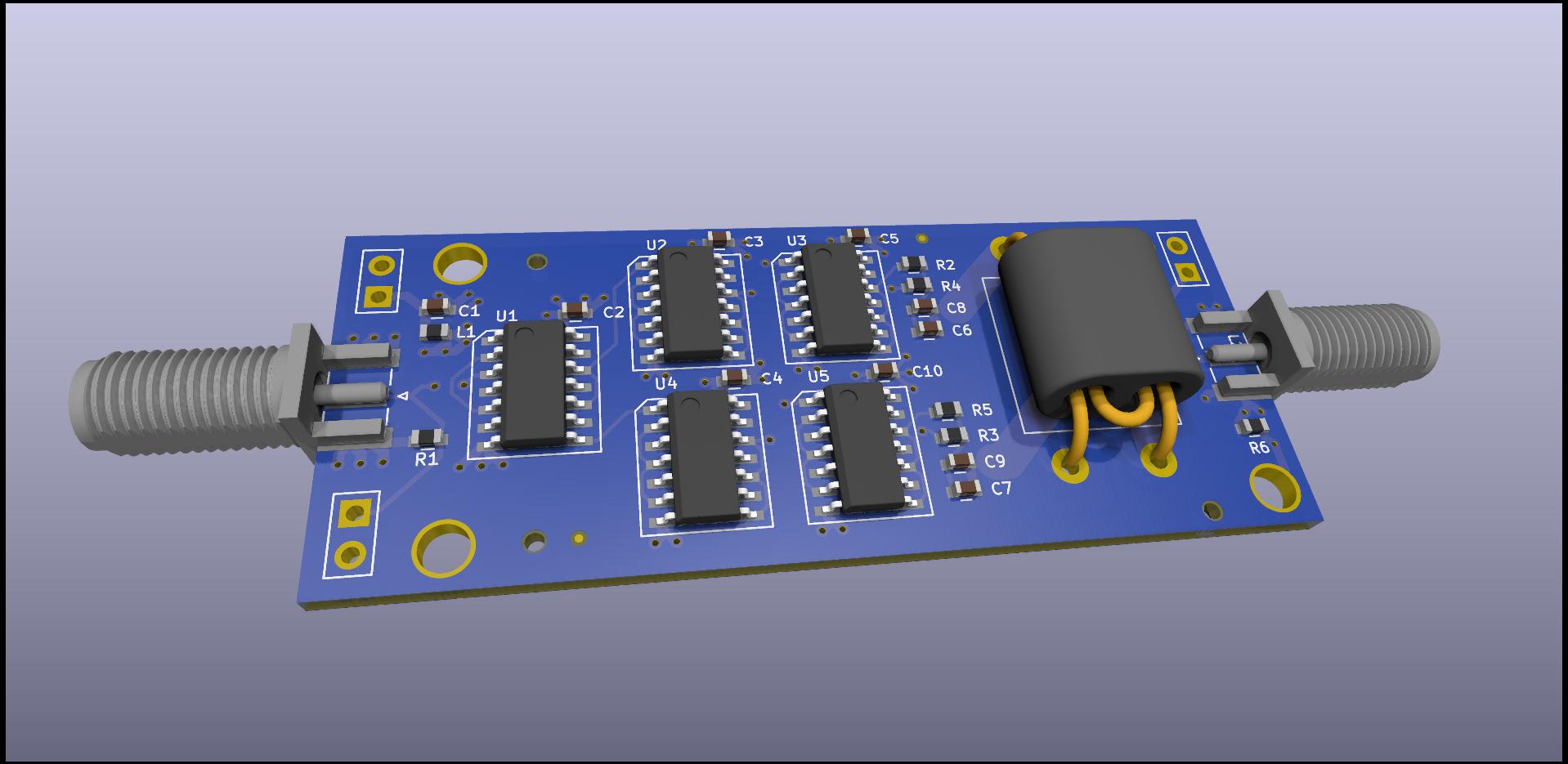
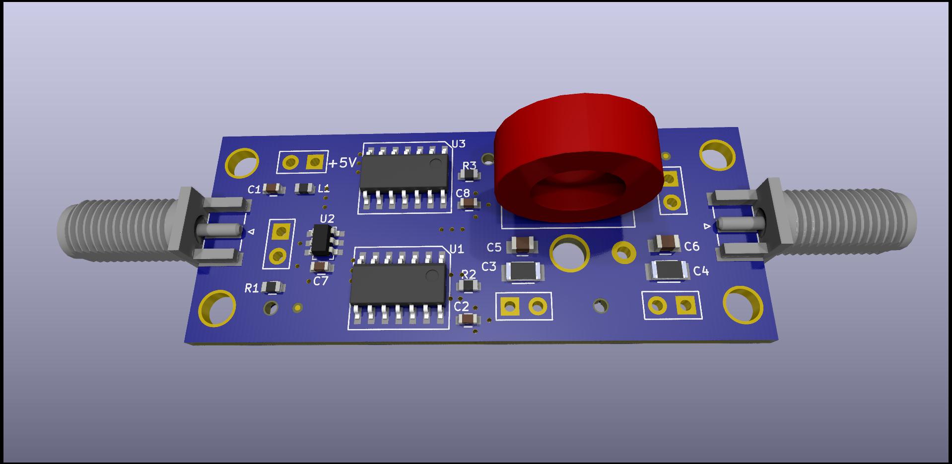
Updated Clock Distribution Buffer:
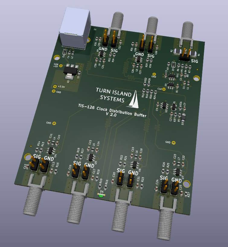
The existing five-output clock buffer has proven quite useful for distributing reference clocks in multiple-SDR receiver systems. Since I am running out of that unit, I have sent this upgraded design for fabrication and assembly. This new design now provides six outputs, each with jumper-selectable AC/DC coupling on both the signal and ground connections. The AC coupling won’t make any difference if you have RF ground-loop issues, but can really help with DC/power supply ground issues (as we often see with USB-powered devices). This new board also provides a power/clock indicator LED.
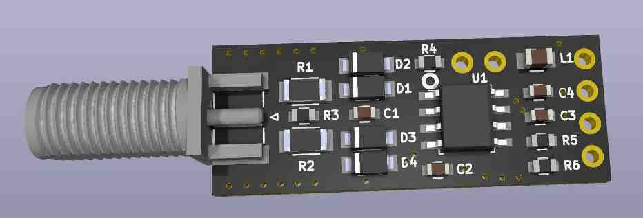
AC-Coupled SMA Adaptor:
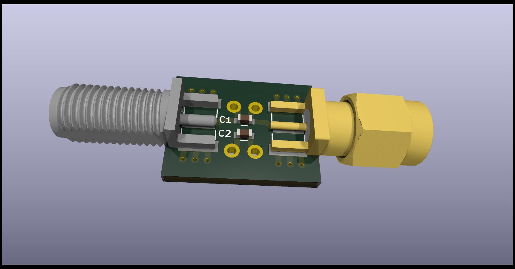
This tiny board provides capacitor-coupling for both signal and ground. While it’s simple, it can be very useful when dealing with grounding issues. Note that the commonly-available DC-block adaptors only block the signal pin, and still leave the grounds connected.
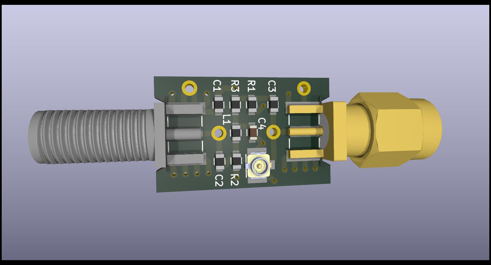
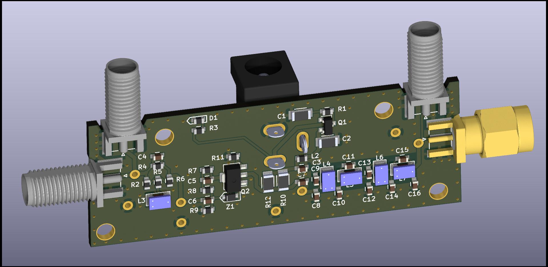
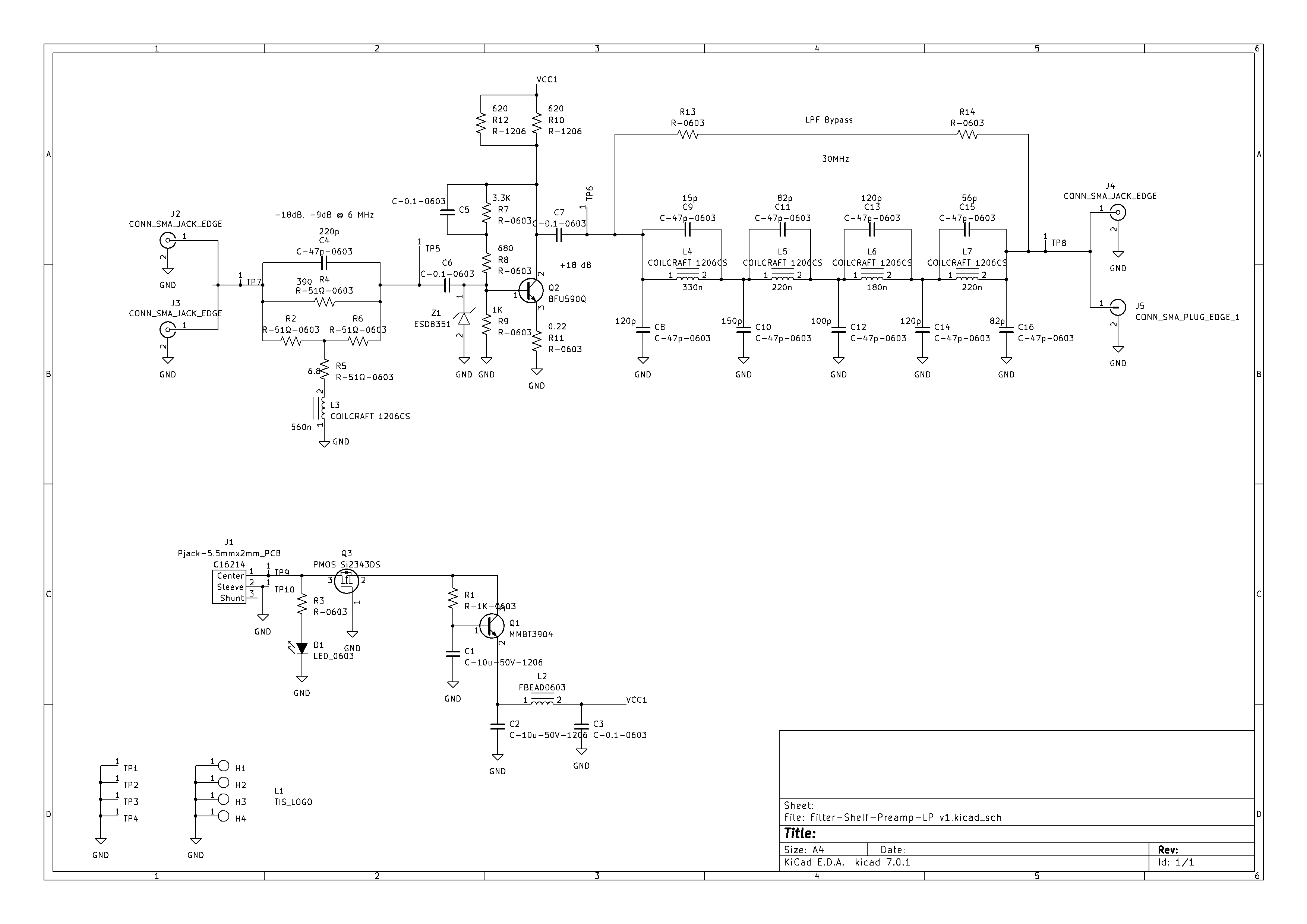
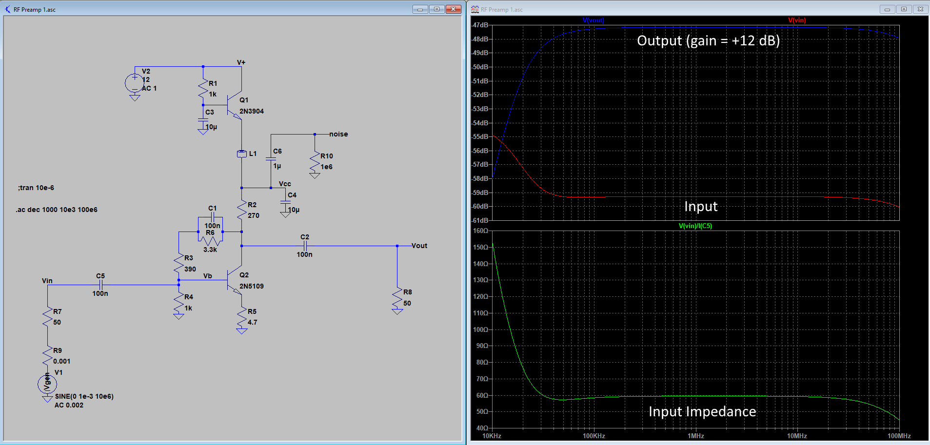
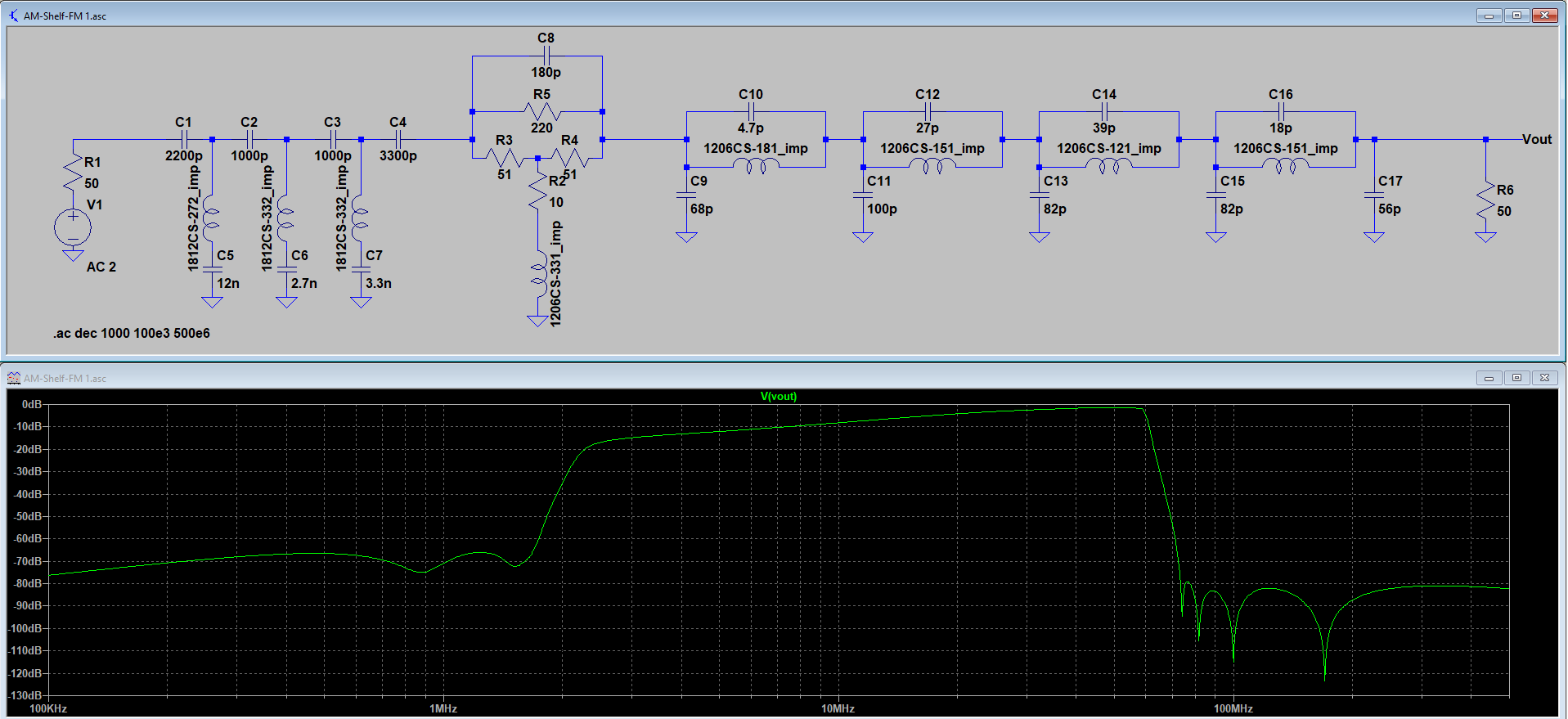
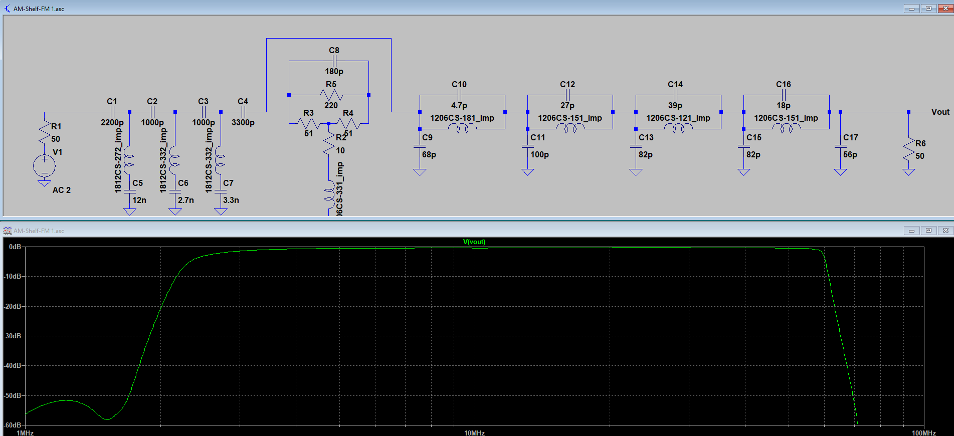
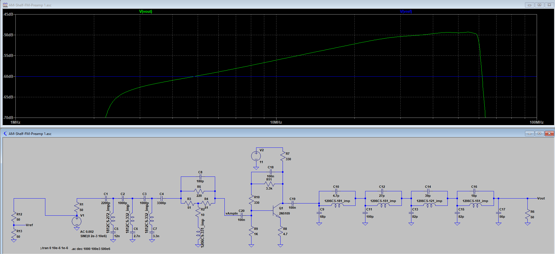
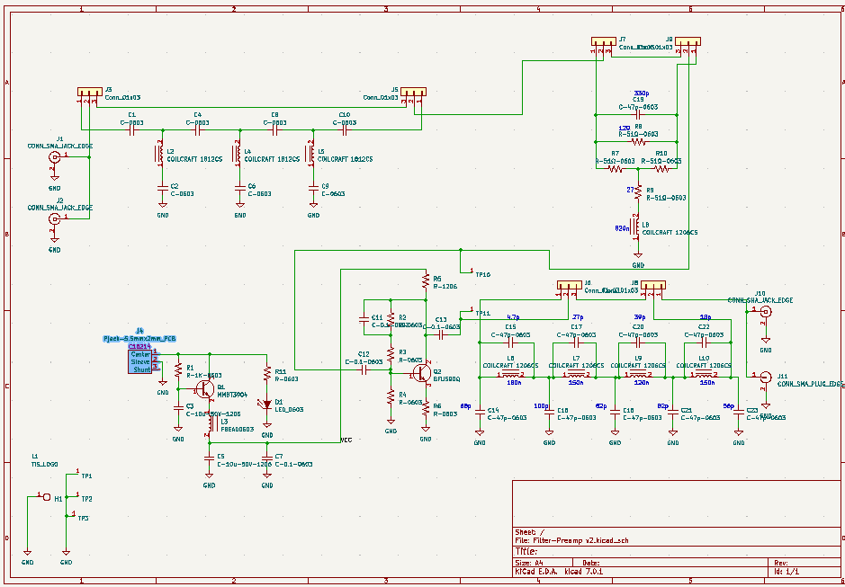
Filter/Preamp V2:
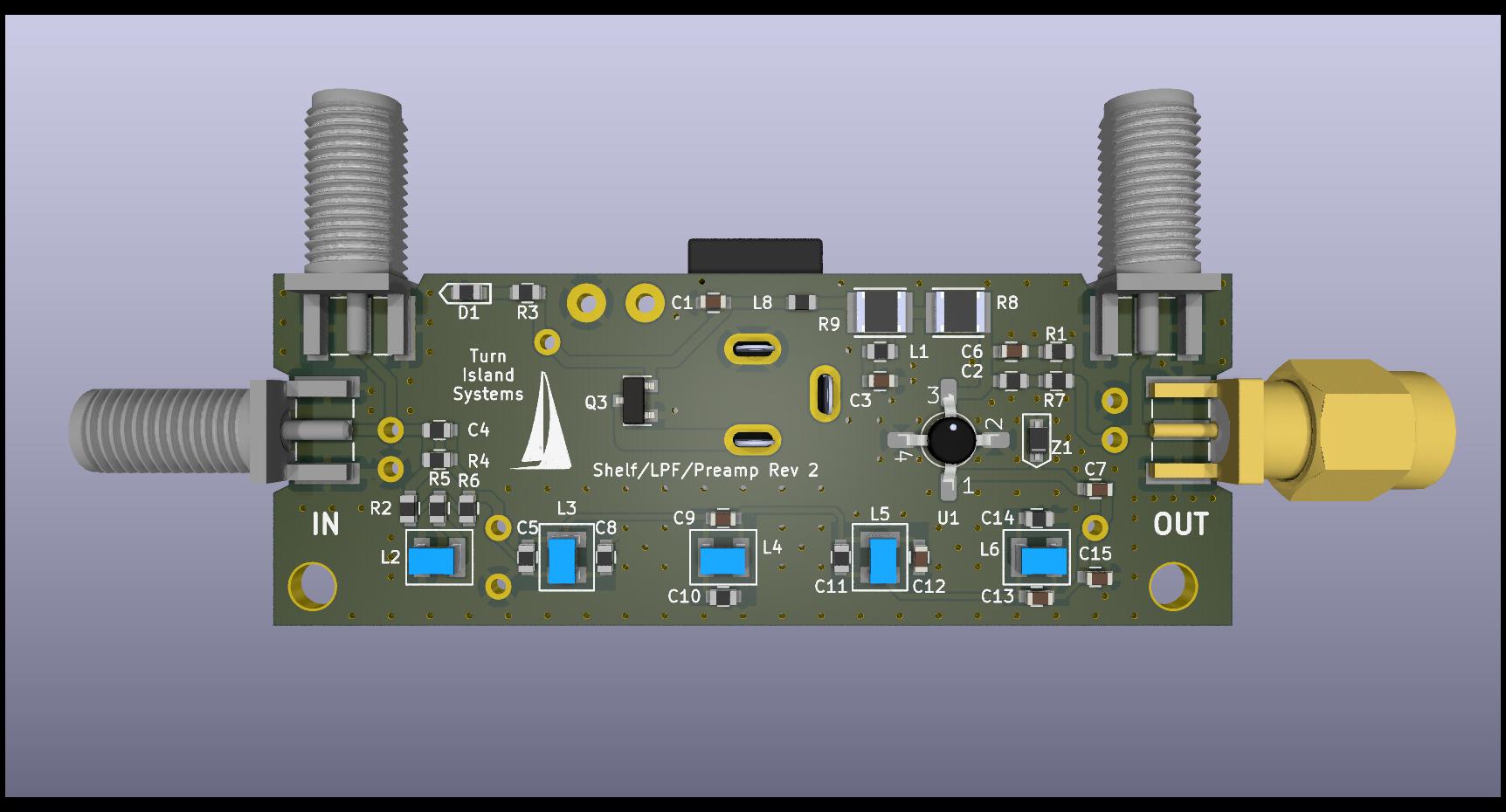
This is my second try with the filter-preamp. I have rearranged the low-pass filter to (I hope) reduce blow-by, and have upgraded the amplifier to use a Minicircuits MAV-11BSM+ device. This should improve the intermodulation distortion and provide a good noise figure. I have also moved the amplifier to the output of the low-pass filter, to reduce potential out-of-band overload issues.
The SMA jack and plug positions provide the option for the in-line jack/plug and right-angle jack/jack configurations.
I may eventually replace the MAV-11 amplifier with a high-speed current-feedback amplifier, which should result in excellent distortion numbers, reasonable noise figure, and lower power consumption. But for now the current design should be a good performer, and I want to verify the performance of the new filter arrangement.


 Direct Interface Board
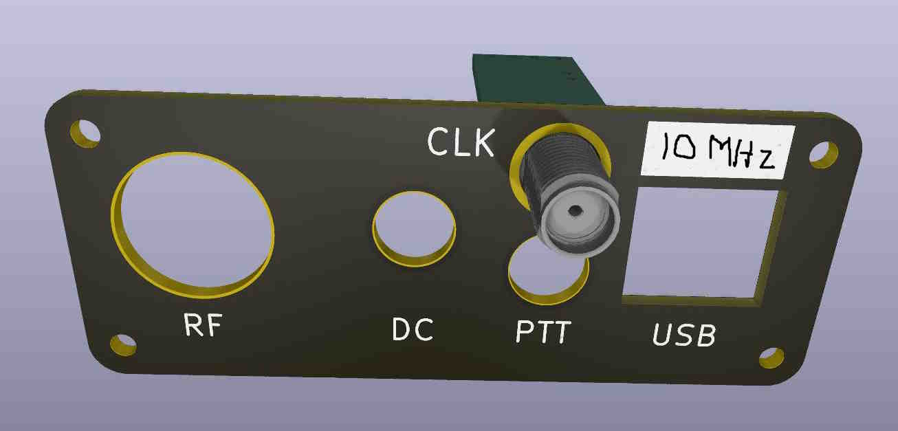