Category Archives: FST4W

SDR Dynamic Range, Filters, and Broadcast Band Transmitters

As we push the envelope of SDR bandwidth with receivers like the RX-888, In addition to sample rate and aliasing concerns we also also need to look at the dynamic range issues.  With traditional “analog” receivers the dynamic range is usually dominated by the IMD (intermodulation distortion) of the  front-end preamp and the following mixer stage.  Techniques to optimize dynamic range include  pre-filtering and AGC (automatic gain control), which can be quite effective when used in relatively narrow-band operation.

But AGC and filtering aren’t so easy in a SDR that is receiving the entire spectrum from (say) 10 KHz to 60 MHz.  There is a huge range of signal levels, especially when you are close to a megawatt-level broadcast transmitter.  While the 16-bit ADC (analog to digital converter) in the RX-888, with it’s 96dB range, is clearly superior to the 12 and 8-bit ADCs used in many other SDRs, the real-world range of RF signals can easily exceed this.

By the way, the effective dynamic range of an ADC is often several dB better than is suggested by the number of bits, due to what is essentially noise dithering and oversampling.

In some cases the programmable attenuation provided by the SDR can be adjusted dynamically for the best use of the available dynamic range.  In addition, there is always the possibility of digital overload and/or digital gain control via numerical scaling within the numerous digital signal processing stages of the software.  These are subjects for a different discussion.  Here, I’m talking about filters.

While some amount of ADC over-range clipping is tolerable, we usually try to minimize this by inserting attenuation or otherwise setting the gain before the ADC sufficient to avoid significant overloads.  We also use a moderate amount of frequency-shaped filtering to reduce input levels at lower frequencies where the general atmospheric noise establishes a higher noise floor.  The Turn Island Systems SDR Filter and Filter-Preamp are examples of this type of filtering:
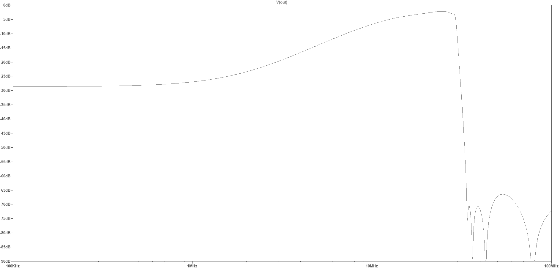
Shelf filter with 30 MHz anti-alias LPF

This filter has a steep 30 MHz anti-aliasing low-pass filter, and a high-pass “shelf” filter that attenuates the frequencies below around 10 MHz, flattening out below 1 MHz to a “shelf” attenuation of about 28 dB.  This shelf filter roughly compensates for the change in the general atmospheric noise level, and attenuates the USA AM BCB (broadcast band, 540 – 1700 KHz) , helping reduce the chance of ADC overload.

A similar filter/preamp (under development) places the LPF corner frequency at 60 MHz, allowing reception of the 6-meter ham band (requiring a RX-888 SDR sample rate of 130 MHz).  This filter also has the stopband notches placed to optimize attenuation of the 88 – 108 MHz FM broadcast band, which would otherwise be aliased down to 22 – 42 MHz in frequency.  While the RX-888 does have a built-in 60 MHz LPF, it’s characteristics are pretty marginal (see the links at the end of this post for more details).
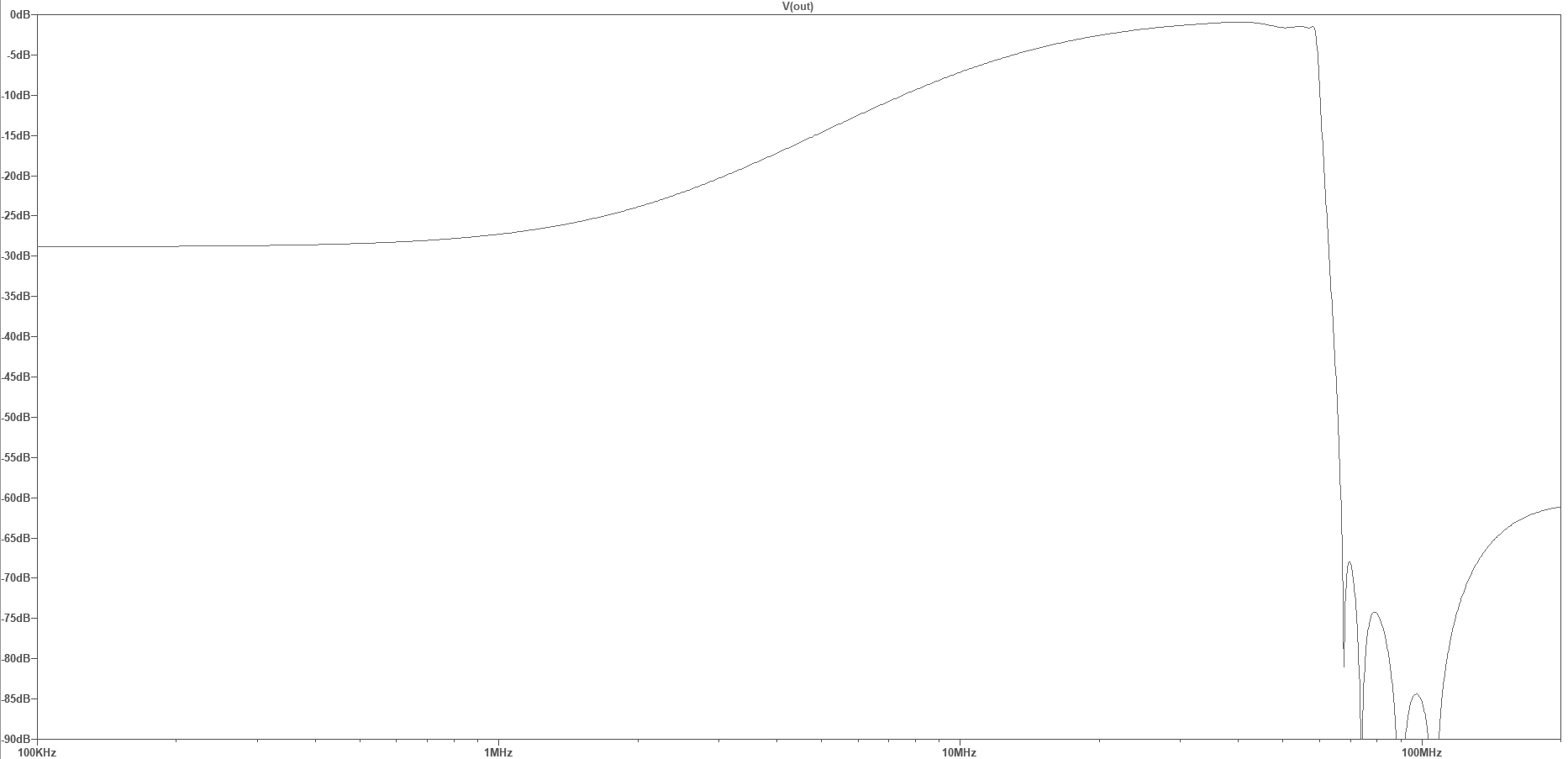
Shelf filter with 60 MHz anti-alias LPF

While the shelf filter reduces the chance of AM BCB overload, strong signals elsewhere can still cause problems.  If these are in the ham bands then simple filtering is not going to help.  But some people are using tunable notch-filters to attenuate specific signals, or ham-band bandpass filters to attenuate out-of-band signals.  Here is an eight-band bandpass filter I am currently working on (I’m calling it the BPF8):

The BPF8 is actually a bank of three-section bandpass filters connected in parallel.  Each filter has this design:

One of the eight band-pass filters

The (simulated) overall response looks like this, covering the 80, 40, 30, 20, 18, 15, 12, and 10 meter ham bands.  These filters are tuned for the WSPR sub-bands:
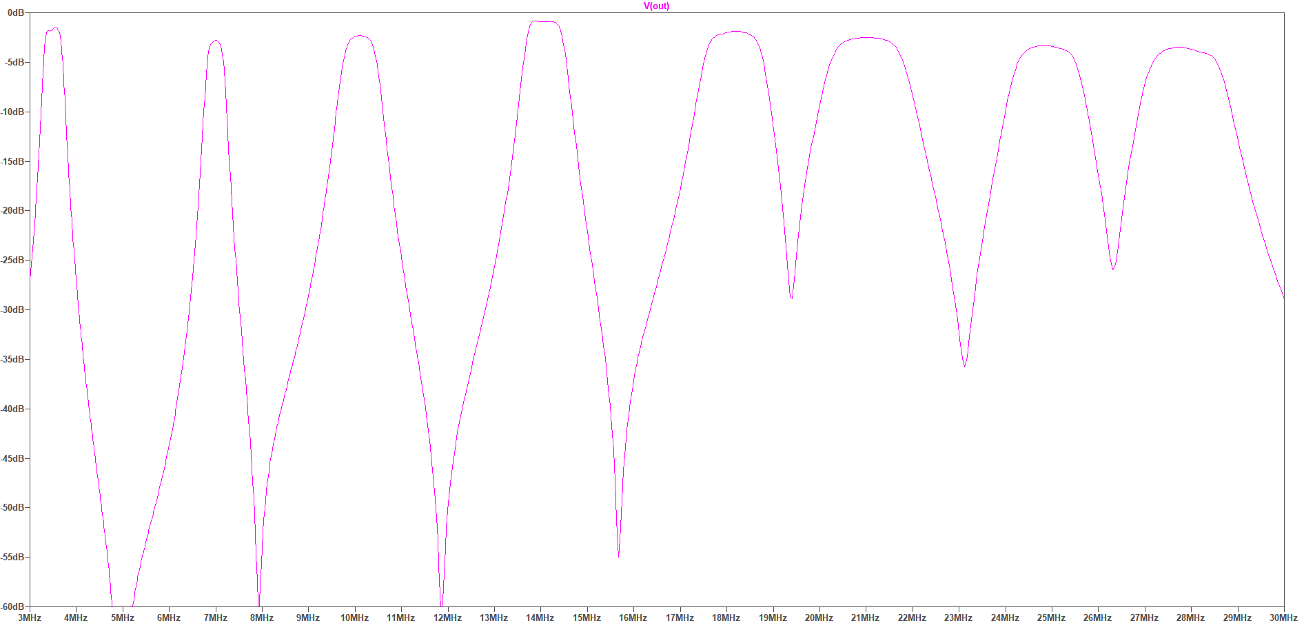
BPF8 frequency response (linear frequency plot)

Will this help with SDR dynamic range?  That depends on the interference — if the out of band signals aren’t strong enough to create problems then this filter will be unnecessary.

If reception between the filter bands is still desired, a broadband shelf response can be selected (via a jumper), which limits the maximum attenuation — here, to 30 dB:
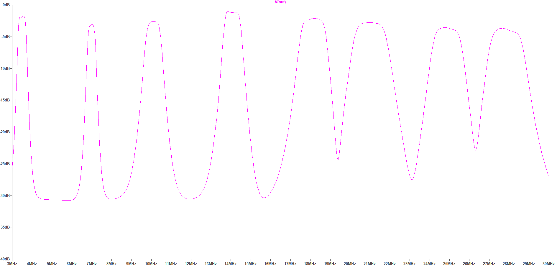
BPF8 frequency response, -30dB shelf (linear frequency plot)

In the USA, most of the BCB signals are below that 1700 KHz frequency. But in Europe there are many powerful broadcast transmitters scattered over the HF frequencies, and these can cause big dynamic range problems.  Here are the shortwave BCB frequency bands superimposed on the above multiband filter response (some of these bands are only lightly or regionally in use):
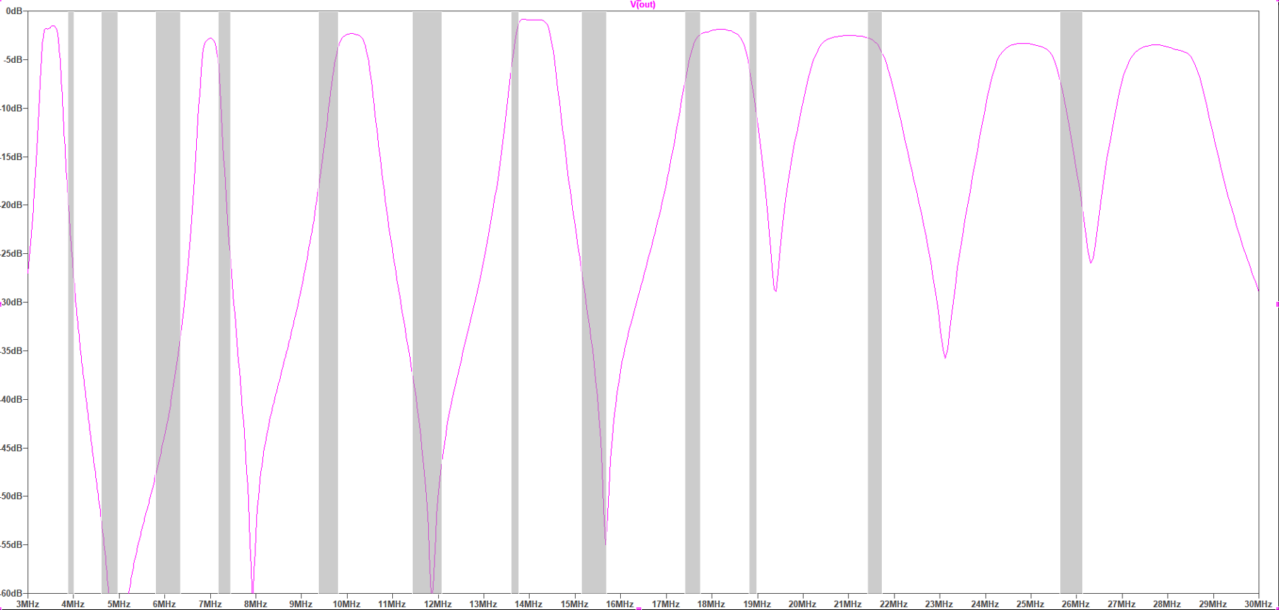
Shortwave broadcast bands

As you can see, some of these SW BCB frequencies are extremely close to the ham bands, and so in those cases the filter will probably not help much, while other SW BCB signals will be significantly attenuated.  The  BPF8 will probably include jumper options to optionally disable a selected filter section. Is the BPF8 worth a try?  We shall see.
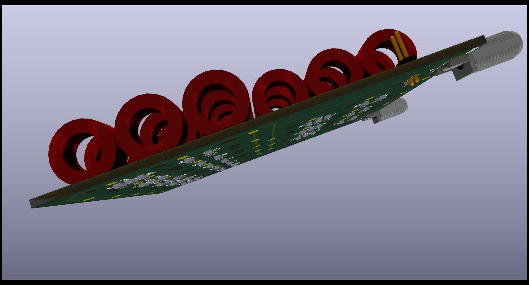
BPF8 circuit board
BPF8 circuit board

The BPF8 prototype board is densely populated with 24 toroid core inductors, used for their low-loss and self-shielding characteristics.  The filter capacitors are on the underside of the board.  This will be another “hard to build” design, because of all the hand-wound and tuned toroids, but I hope the results will be worth it.

For more details of the RX-888, and about shelf filters, look at KA7OEI’s blog for some excellent in-depth discussion of these issues:

measuring-signal-dynamics-of-rx-888-mk2

frequency-response-of-rx-888

revisiting-limited-attenuation-high-pass-filter

International broadcast bands:

International_broadcast_bands (Wikipedia)
 

FST4W-120 on Ten Bands Simultaneously

As you may know, over at Turn Island Systems (TIS) we have developed the WSPRSONDE-8 (WS-8), a multi-channel transmitter used in ionospheric propagation measurements.  This transmitter has eight channels, each covering 160 to 6 meters (and all frequencies in-between), each channel capable of transmitting at the same time.  Typically some or all of these outputs are combined to feed a single multi-band antenna, using one of the TIS filter-combiner boxes.  The WS-8 and earlier incarnations are currently transmitting at locations on multiple continents, in support of the HamSci ionospheric study programs.

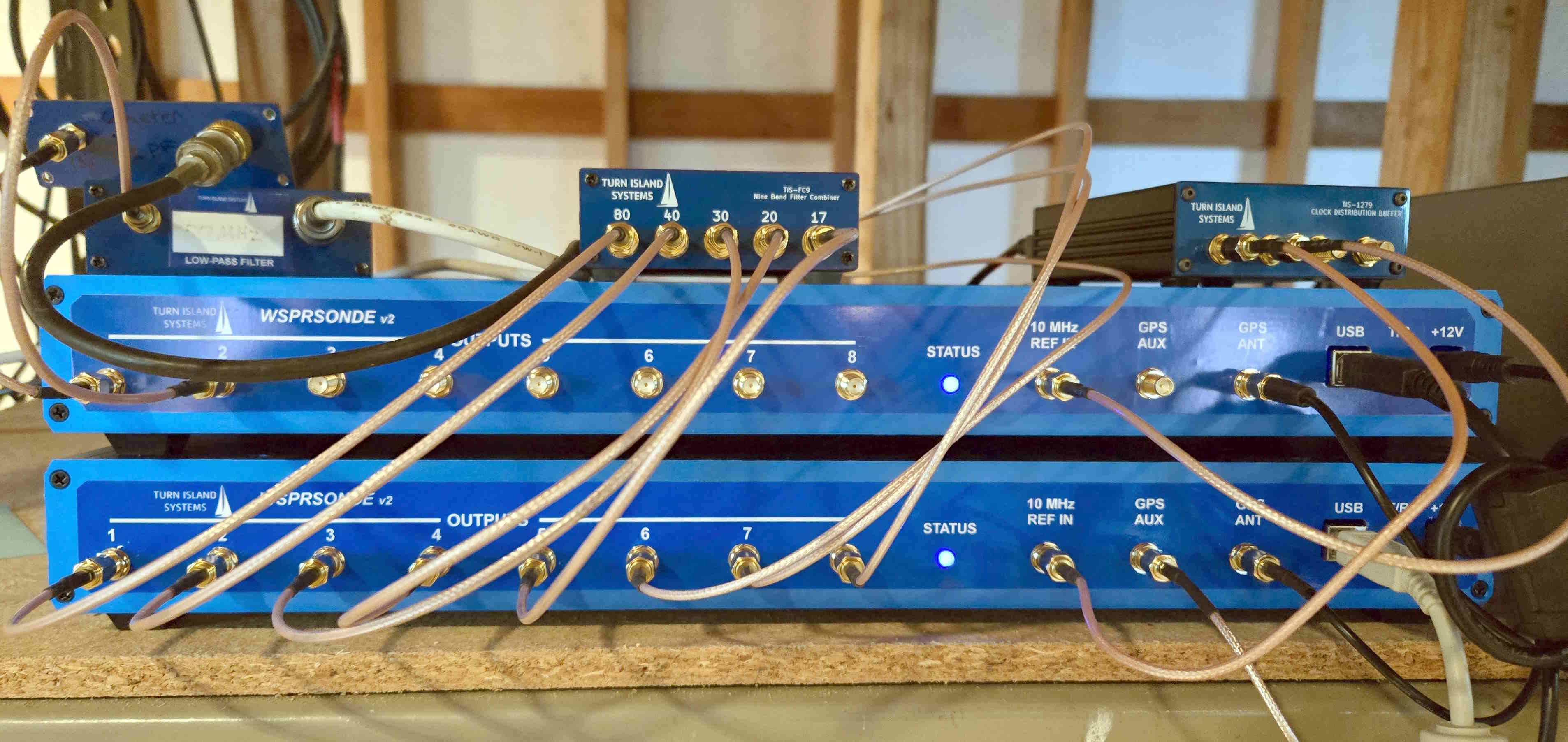
TIS has a test site near Occidental, California where I have a number of antennas and now two WS-8 transmitters.  One antenna is the EFHW-8010 from myantennas.com, and this is being driven by one WS-8 through a prototype nine-band Filter-Combiner.  The frequencies are 80/40/30/20/17/15/12/10 meters.

The second WS-8 is driving two dipoles, one for 160 meters, and the other for 6 meters.

Here is the new setup: Two WS

The little boxes on top of the WS-8 stack are (left to right):

  • 160 meter Low Pass filter — This is a L/C/L/C filter, with a few dB of peaking.  I used T50-2 toroids for the inductors.  The input series inductor reduces the loading on the WS8 power amplifier (the strong third harmonic sees a rather high impedance).  Harmonic suppression is better than -50 dBc.
  • 6 meter Low Pass Filter.   This is a simple L/C/L TEE filter, again using toroids (T50-6).
  • 9-Band Filter-Combiner.  There is a description of this on the Turn Island Systems website.
  • Clock Distribution Buffer (a predecessor to the TIS-126).  This is taking the output of a Bodnar GPSDO and sending it to the two WS8 units.

If you care to listen to these transmitters, here are the frequencies (“tone 0″ of the FST4W 4FSK):

WS8 #1 (EFHW-8010): 
Channel 1, frequency: 3,570,135.000000 Hz 
Channel 2, frequency: 7,040,134.926829 Hz 
Channel 3, frequency: 10,140,234.959350 Hz 
Channel 4, frequency: 14,097,134.959350 Hz 
Channel 5, frequency: 18,106,134.878049 Hz 
Channel 6, frequency: 21,096,134.878049 Hz 
Channel 7, frequency: 24,926,134.869041 Hz 
Channel 8, frequency: 28,126,134.634146 Hz 
 
WS8 #2: 
Channel 1, frequency: 1,838,134.982578 Hz
Channel 2, frequency: 50,294,534.290017 Hz

HamSCI, AGU, WSPRSONDE-8

Good friend Rob Robinett (developer of wsprdaemon), along with leaders of the HamSCI Citizen Science Project, are at the American Geophysical Union (AGU) annual meeting in San Francisco, showing how WSPR is being used to study the behavior of the ionosphere.  One of the posters being exhibited features the WSPRSONDE-8   multi-channel transmitter currently in development at Turn Island Systems:

Poster

See more WSPRSONDE-8 information at TurnIslandSystems.com

Rant: WSPR and FST4W Timing — Why???

In this post I complain about the symbol-rate timing of the various FST4W rates.  I am adding WSPR and other FST4W rates to the Beacon Blaster ( which currently generates FST4W-120, see https://turnislandsystems.com/ for details) and am getting very annoyed with the timing variations.

So let’s start with WSPR.  The symbol rate is approximately 1.4648 baud (4FSK symbols per second), or exactly 12,000 Hz / 8192.  The FSK shift is the reciprocal of this, or about 0.6827 Hz.

OK, I have no complaints about this, the numbers are easy to work with and “8192″ is a nice power of two.  This makes it easy to use a timer-interrupt to run a digital filter at (say) 64x the symbol rate.  But really, any values for that 12,000 / 8192 fraction would be workable if WSPR were the only concern.

Now, look at the FST4W rates (from the wsjtx source code):

 if(mode=="FST4" or mode=="FST4W") { //FST4, FST4W
   if(trPeriod==15) txt=1.0 + 160*720/12000.0;
   if(trPeriod==30) txt=1.0 + 160*1680/12000.0;
   if(trPeriod==60) txt=1.0 + 160*3888/12000.0;
   if(trPeriod==120) txt=1.0 + 160*8200/12000.0;
   if(trPeriod==300) txt=1.0 + 160*21504/12000.0;
   if(trPeriod==900) txt=1.0 + 160*66560/12000.0;
   if(trPeriod==1800) txt=1.0 + 160*134400/12000.0;
 }

I assume “txt” means “transmit time”.  “160″ is the number of symbols in a message.  So the symbol rates are:

FST4-15:   12,000 / 720
FST4-30:   12,000 / 1,680
FST4-60:   12,000 / 3,888
FST4W-120: 12,000 / 8,200
FST4W-300: 12,000 / 21,504
FST4W-900: 12,000 / 66,530
FST4W-1800: 12,000 / 134,400

For the four FST4W rates, the divisors are 8200, 21504, 66540, and 134400.  The only common factor is 2.  And at that common rate of 12,000 / 2 there is no hope of programming the clock-generator chips, especially since the different symbol times drift past  each other.

Since the symbol-rate accuracy is critical to the kind of propagation measurements we are using FST4W for, I am stuck running different timer interrupt rates for each mode and speed, and only running one mode at a time.  Why didn’t they use something like this instead?

CXC4-15:   12,000 / 512
CXC4-30:   12,000 / 1,024
CXC4-60:   12,000 / 4,096
CXC4W-120: 12,000 / 8,192
CXC4W-300: 12,000 / 20.480
CXC4W-900: 12,000 / 61.440
CXC4W-1800: 12,000 / 122,880

Sure, in most modes the gaps between transmissions become a bit larger, but if this is an issue then pick some other numbers.  But at least have them related by a larger common factor!

*END OF RANT*