Category Archives: WSPR

SDR Dynamic Range, Filters, and Broadcast Band Transmitters

As we push the envelope of SDR bandwidth with receivers like the RX-888, In addition to sample rate and aliasing concerns we also also need to look at the dynamic range issues.  With traditional “analog” receivers the dynamic range is usually dominated by the IMD (intermodulation distortion) of the  front-end preamp and the following mixer stage.  Techniques to optimize dynamic range include  pre-filtering and AGC (automatic gain control), which can be quite effective when used in relatively narrow-band operation.

But AGC and filtering aren’t so easy in a SDR that is receiving the entire spectrum from (say) 10 KHz to 60 MHz.  There is a huge range of signal levels, especially when you are close to a megawatt-level broadcast transmitter.  While the 16-bit ADC (analog to digital converter) in the RX-888, with it’s 96dB range, is clearly superior to the 12 and 8-bit ADCs used in many other SDRs, the real-world range of RF signals can easily exceed this.

By the way, the effective dynamic range of an ADC is often several dB better than is suggested by the number of bits, due to what is essentially noise dithering and oversampling.

In some cases the programmable attenuation provided by the SDR can be adjusted dynamically for the best use of the available dynamic range.  In addition, there is always the possibility of digital overload and/or digital gain control via numerical scaling within the numerous digital signal processing stages of the software.  These are subjects for a different discussion.  Here, I’m talking about filters.

While some amount of ADC over-range clipping is tolerable, we usually try to minimize this by inserting attenuation or otherwise setting the gain before the ADC sufficient to avoid significant overloads.  We also use a moderate amount of frequency-shaped filtering to reduce input levels at lower frequencies where the general atmospheric noise establishes a higher noise floor.  The Turn Island Systems SDR Filter and Filter-Preamp are examples of this type of filtering:
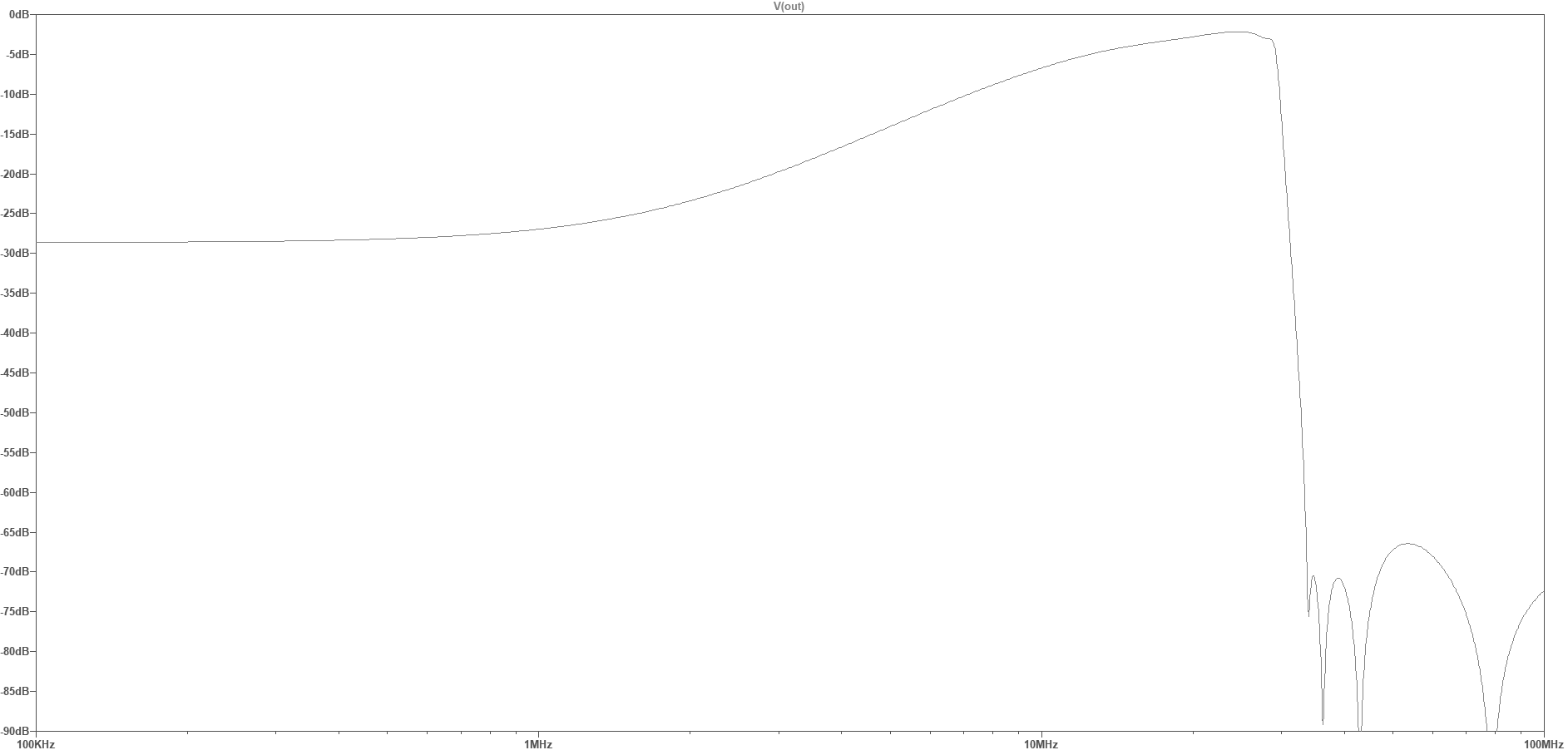
Shelf filter with 30 MHz anti-alias LPF

This filter has a steep 30 MHz anti-aliasing low-pass filter, and a high-pass “shelf” filter that attenuates the frequencies below around 10 MHz, flattening out below 1 MHz to a “shelf” attenuation of about 28 dB.  This shelf filter roughly compensates for the change in the general atmospheric noise level, and attenuates the USA AM BCB (broadcast band, 540 – 1700 KHz) , helping reduce the chance of ADC overload.

A similar filter/preamp (under development) places the LPF corner frequency at 60 MHz, allowing reception of the 6-meter ham band (requiring a RX-888 SDR sample rate of 130 MHz).  This filter also has the stopband notches placed to optimize attenuation of the 88 – 108 MHz FM broadcast band, which would otherwise be aliased down to 22 – 42 MHz in frequency.  While the RX-888 does have a built-in 60 MHz LPF, it’s characteristics are pretty marginal (see the links at the end of this post for more details).
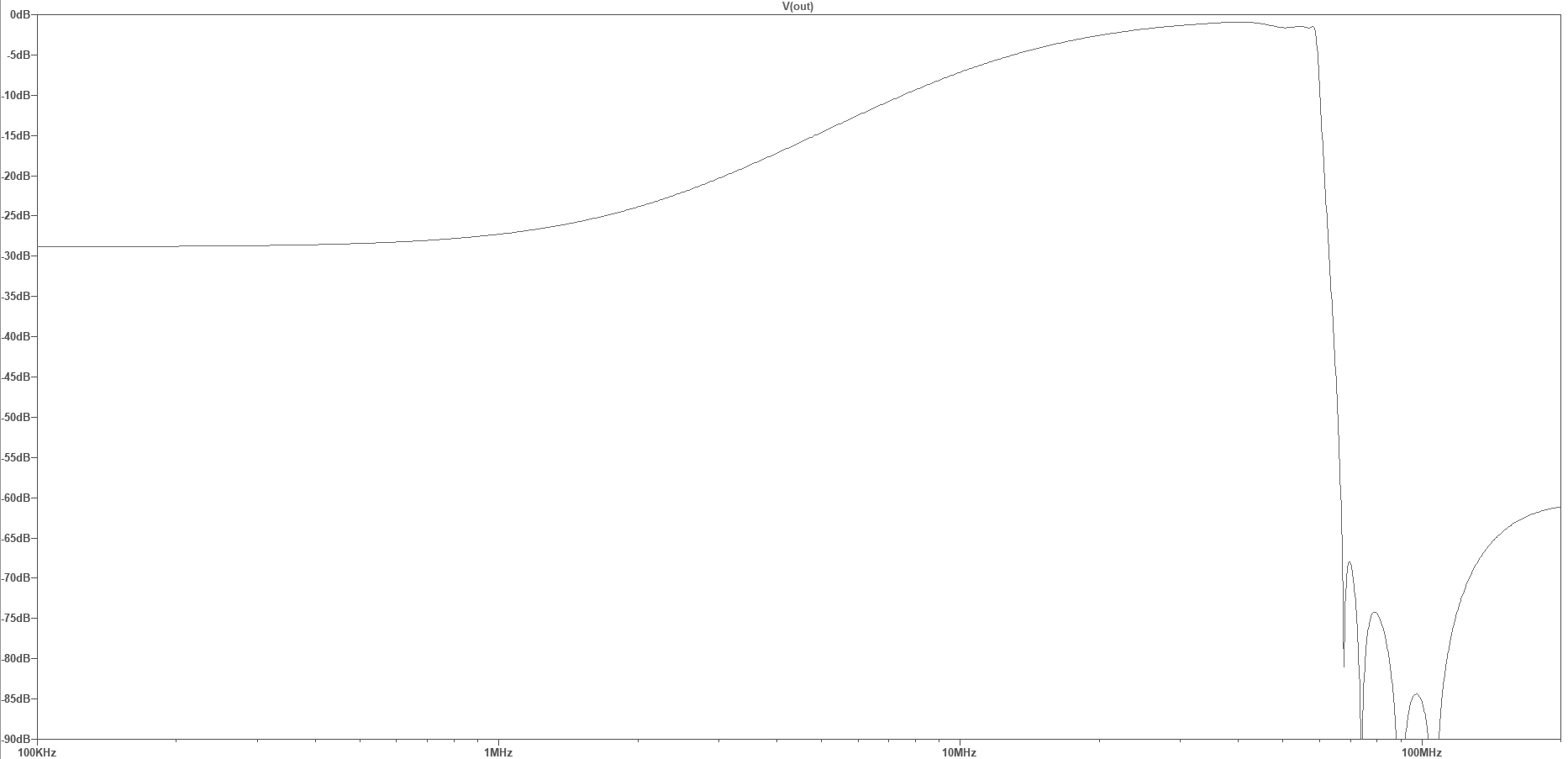
Shelf filter with 60 MHz anti-alias LPF

While the shelf filter reduces the chance of AM BCB overload, strong signals elsewhere can still cause problems.  If these are in the ham bands then simple filtering is not going to help.  But some people are using tunable notch-filters to attenuate specific signals, or ham-band bandpass filters to attenuate out-of-band signals.  Here is an eight-band bandpass filter I am currently working on (I’m calling it the BPF8):

The BPF8 is actually a bank of three-section bandpass filters connected in parallel.  Each filter has this design:

One of the eight band-pass filters

The (simulated) overall response looks like this, covering the 80, 40, 30, 20, 18, 15, 12, and 10 meter ham bands.  These filters are tuned for the WSPR sub-bands:
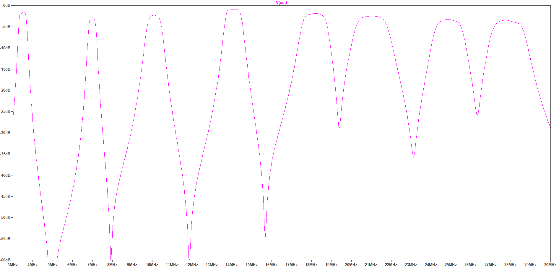
BPF8 frequency response (linear frequency plot)

Will this help with SDR dynamic range?  That depends on the interference — if the out of band signals aren’t strong enough to create problems then this filter will be unnecessary.

If reception between the filter bands is still desired, a broadband shelf response can be selected (via a jumper), which limits the maximum attenuation — here, to 30 dB:
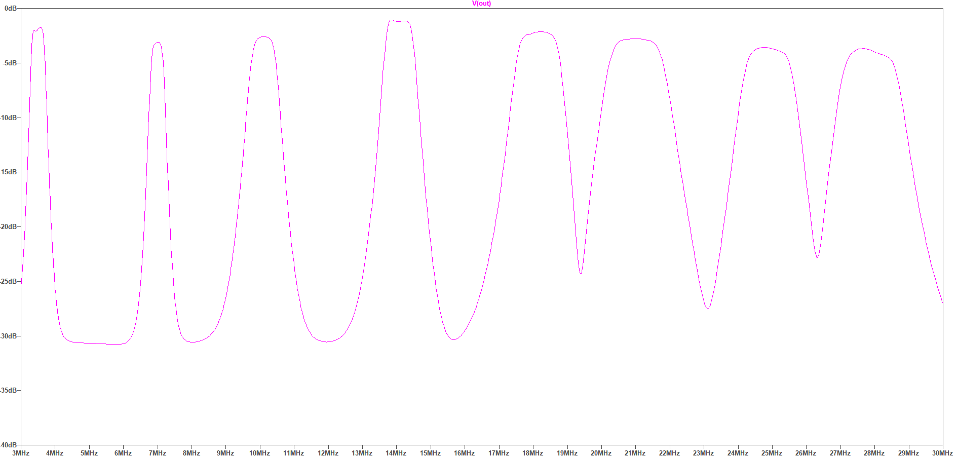
BPF8 frequency response, -30dB shelf (linear frequency plot)

In the USA, most of the BCB signals are below that 1700 KHz frequency. But in Europe there are many powerful broadcast transmitters scattered over the HF frequencies, and these can cause big dynamic range problems.  Here are the shortwave BCB frequency bands superimposed on the above multiband filter response (some of these bands are only lightly or regionally in use):
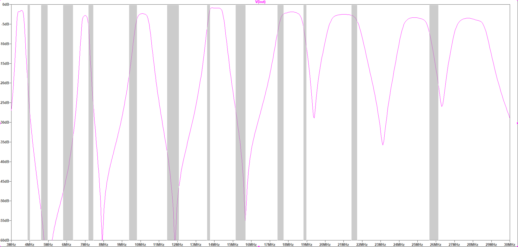
Shortwave broadcast bands

As you can see, some of these SW BCB frequencies are extremely close to the ham bands, and so in those cases the filter will probably not help much, while other SW BCB signals will be significantly attenuated.  The  BPF8 will probably include jumper options to optionally disable a selected filter section. Is the BPF8 worth a try?  We shall see.
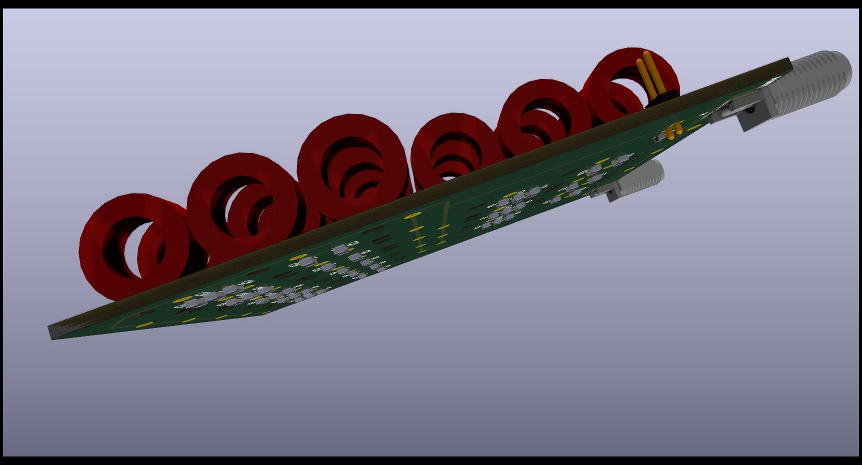
BPF8 circuit board
BPF8 circuit board

The BPF8 prototype board is densely populated with 24 toroid core inductors, used for their low-loss and self-shielding characteristics.  The filter capacitors are on the underside of the board.  This will be another “hard to build” design, because of all the hand-wound and tuned toroids, but I hope the results will be worth it.

For more details of the RX-888, and about shelf filters, look at KA7OEI’s blog for some excellent in-depth discussion of these issues:

measuring-signal-dynamics-of-rx-888-mk2

frequency-response-of-rx-888

revisiting-limited-attenuation-high-pass-filter

International broadcast bands:

International_broadcast_bands (Wikipedia)
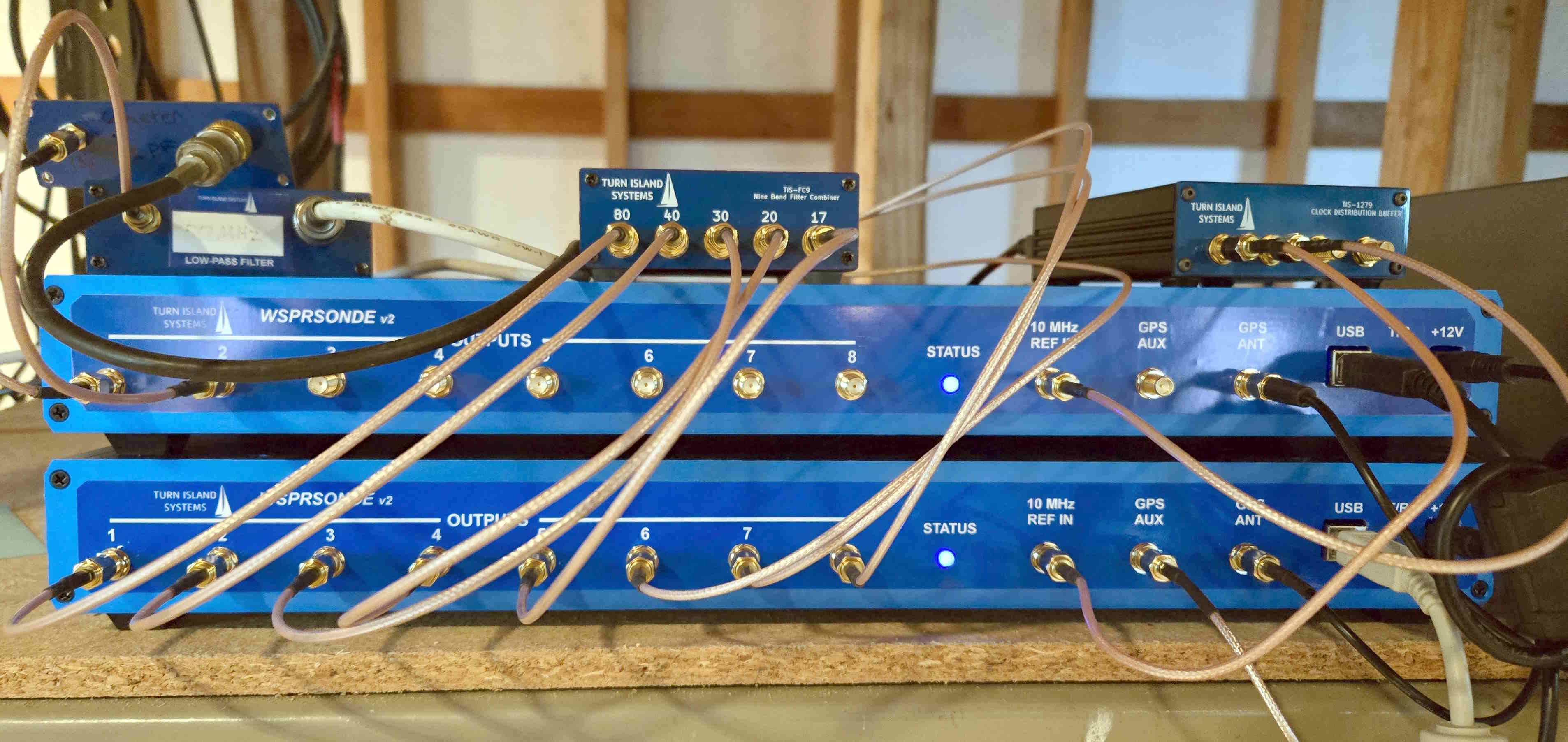
 

FST4W-120 on Ten Bands Simultaneously

As you may know, over at Turn Island Systems (TIS) we have developed the WSPRSONDE-8 (WS-8), a multi-channel transmitter used in ionospheric propagation measurements.  This transmitter has eight channels, each covering 160 to 6 meters (and all frequencies in-between), each channel capable of transmitting at the same time.  Typically some or all of these outputs are combined to feed a single multi-band antenna, using one of the TIS filter-combiner boxes.  The WS-8 and earlier incarnations are currently transmitting at locations on multiple continents, in support of the HamSci ionospheric study programs.

TIS has a test site near Occidental, California where I have a number of antennas and now two WS-8 transmitters.  One antenna is the EFHW-8010 from myantennas.com, and this is being driven by one WS-8 through a prototype nine-band Filter-Combiner.  The frequencies are 80/40/30/20/17/15/12/10 meters.

The second WS-8 is driving two dipoles, one for 160 meters, and the other for 6 meters.

Here is the new setup: Two WS

The little boxes on top of the WS-8 stack are (left to right):

  • 160 meter Low Pass filter — This is a L/C/L/C filter, with a few dB of peaking.  I used T50-2 toroids for the inductors.  The input series inductor reduces the loading on the WS8 power amplifier (the strong third harmonic sees a rather high impedance).  Harmonic suppression is better than -50 dBc.
  • 6 meter Low Pass Filter.   This is a simple L/C/L TEE filter, again using toroids (T50-6).
  • 9-Band Filter-Combiner.  There is a description of this on the Turn Island Systems website.
  • Clock Distribution Buffer (a predecessor to the TIS-126).  This is taking the output of a Bodnar GPSDO and sending it to the two WS8 units.

If you care to listen to these transmitters, here are the frequencies (“tone 0″ of the FST4W 4FSK):

WS8 #1 (EFHW-8010): 
Channel 1, frequency: 3,570,135.000000 Hz 
Channel 2, frequency: 7,040,134.926829 Hz 
Channel 3, frequency: 10,140,234.959350 Hz 
Channel 4, frequency: 14,097,134.959350 Hz 
Channel 5, frequency: 18,106,134.878049 Hz 
Channel 6, frequency: 21,096,134.878049 Hz 
Channel 7, frequency: 24,926,134.869041 Hz 
Channel 8, frequency: 28,126,134.634146 Hz 
 
WS8 #2: 
Channel 1, frequency: 1,838,134.982578 Hz
Channel 2, frequency: 50,294,534.290017 Hz

Rant: WSPR and FST4W Timing — Why???

In this post I complain about the symbol-rate timing of the various FST4W rates.  I am adding WSPR and other FST4W rates to the Beacon Blaster ( which currently generates FST4W-120, see https://turnislandsystems.com/ for details) and am getting very annoyed with the timing variations.

So let’s start with WSPR.  The symbol rate is approximately 1.4648 baud (4FSK symbols per second), or exactly 12,000 Hz / 8192.  The FSK shift is the reciprocal of this, or about 0.6827 Hz.

OK, I have no complaints about this, the numbers are easy to work with and “8192″ is a nice power of two.  This makes it easy to use a timer-interrupt to run a digital filter at (say) 64x the symbol rate.  But really, any values for that 12,000 / 8192 fraction would be workable if WSPR were the only concern.

Now, look at the FST4W rates (from the wsjtx source code):

 if(mode=="FST4" or mode=="FST4W") { //FST4, FST4W
   if(trPeriod==15) txt=1.0 + 160*720/12000.0;
   if(trPeriod==30) txt=1.0 + 160*1680/12000.0;
   if(trPeriod==60) txt=1.0 + 160*3888/12000.0;
   if(trPeriod==120) txt=1.0 + 160*8200/12000.0;
   if(trPeriod==300) txt=1.0 + 160*21504/12000.0;
   if(trPeriod==900) txt=1.0 + 160*66560/12000.0;
   if(trPeriod==1800) txt=1.0 + 160*134400/12000.0;
 }

I assume “txt” means “transmit time”.  “160″ is the number of symbols in a message.  So the symbol rates are:

FST4-15:   12,000 / 720
FST4-30:   12,000 / 1,680
FST4-60:   12,000 / 3,888
FST4W-120: 12,000 / 8,200
FST4W-300: 12,000 / 21,504
FST4W-900: 12,000 / 66,530
FST4W-1800: 12,000 / 134,400

For the four FST4W rates, the divisors are 8200, 21504, 66540, and 134400.  The only common factor is 2.  And at that common rate of 12,000 / 2 there is no hope of programming the clock-generator chips, especially since the different symbol times drift past  each other.

Since the symbol-rate accuracy is critical to the kind of propagation measurements we are using FST4W for, I am stuck running different timer interrupt rates for each mode and speed, and only running one mode at a time.  Why didn’t they use something like this instead?

CXC4-15:   12,000 / 512
CXC4-30:   12,000 / 1,024
CXC4-60:   12,000 / 4,096
CXC4W-120: 12,000 / 8,192
CXC4W-300: 12,000 / 20.480
CXC4W-900: 12,000 / 61.440
CXC4W-1800: 12,000 / 122,880

Sure, in most modes the gaps between transmissions become a bit larger, but if this is an issue then pick some other numbers.  But at least have them related by a larger common factor!

*END OF RANT*


Latest Batch of Boards

I’ve just received another batch of QDX External Reference Interface boards.  More info at Turn Island Systems

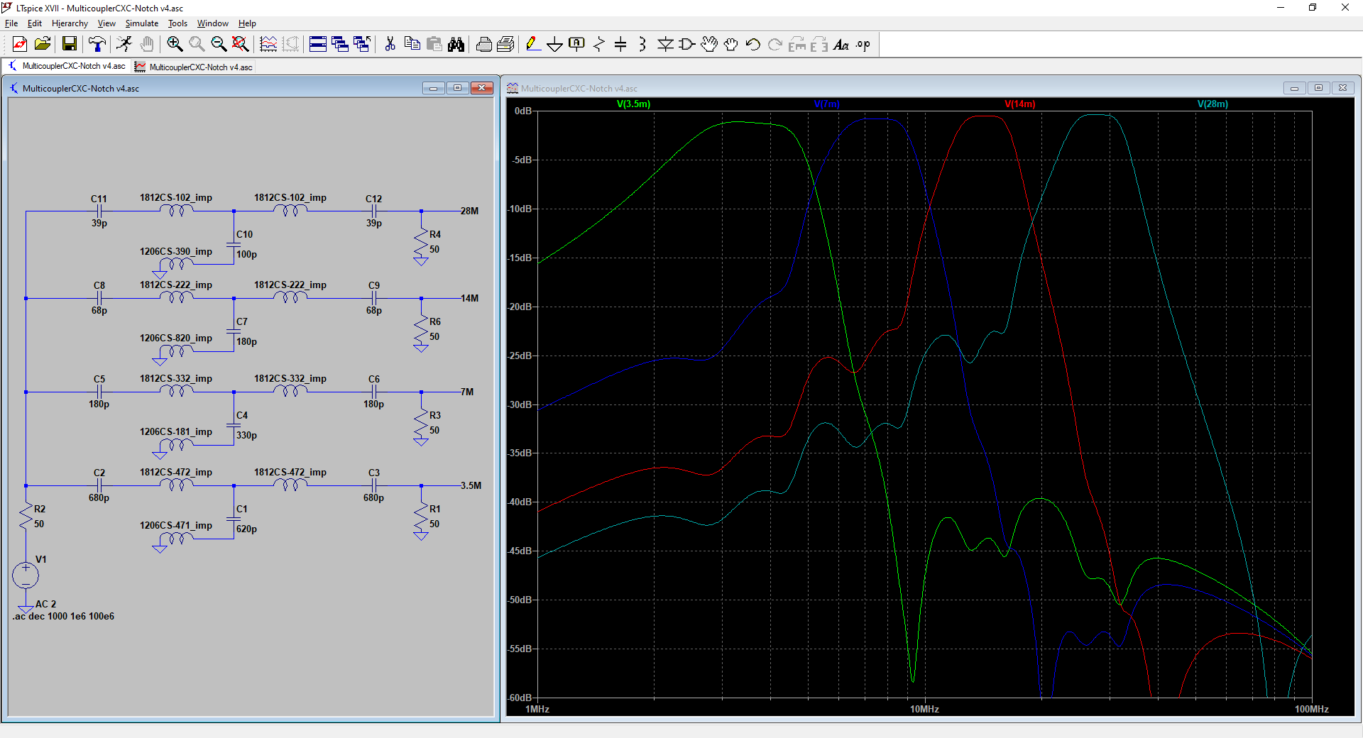
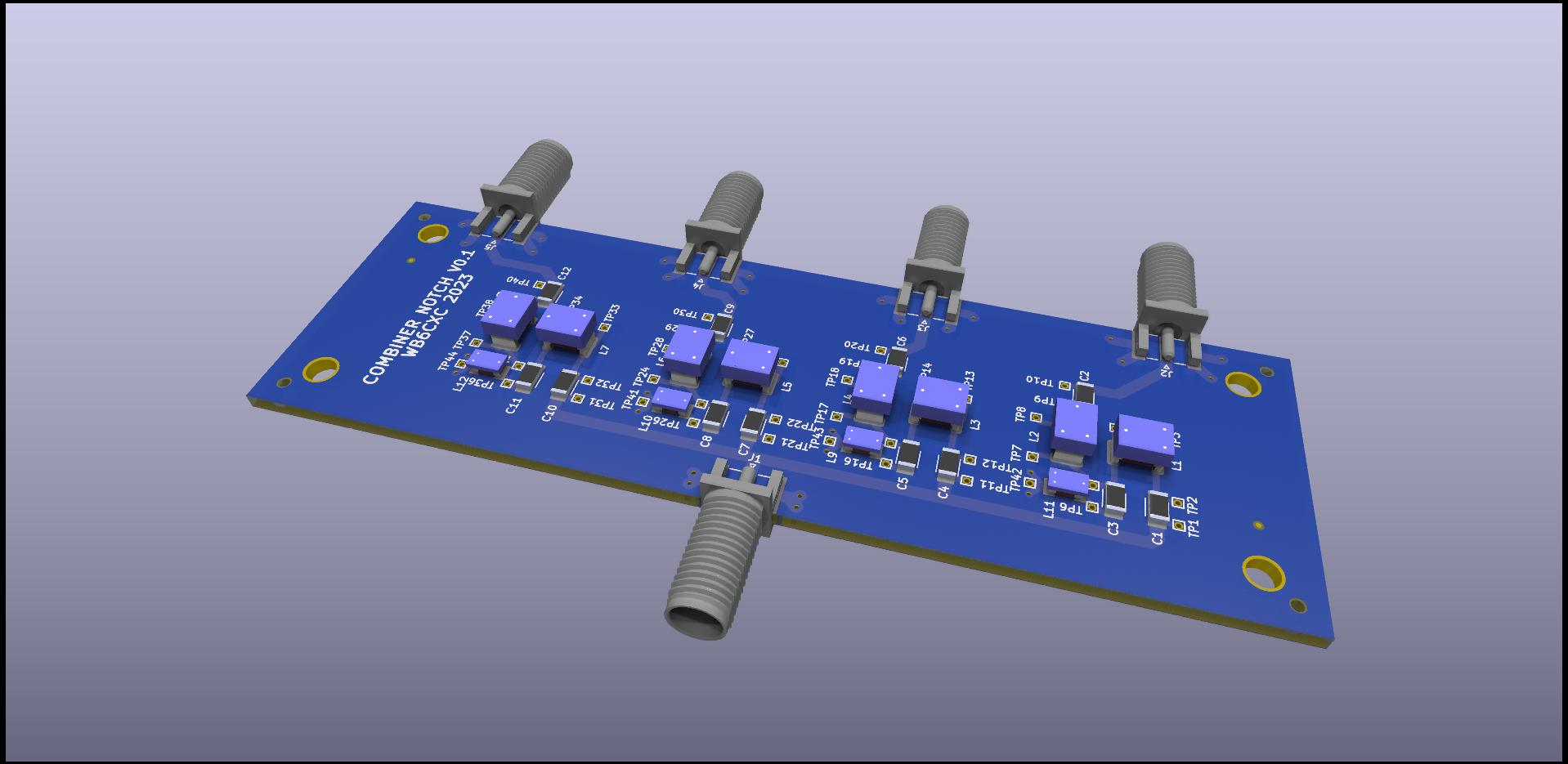
Also, I just sent out boards for a four-channel RF Combiner / Splitter, which takes four 1W (or lower) signals (80, 40, 20, and 10 meters), and combined them into a single output for feeding a multiband antenna.  These provide at least 20dB port-port isolation, and less than 2dB loss.  If all works as planned, these will be used for Ionospheric research.

MC-CXC-Notch

RF Combiner Notch v0.1 top

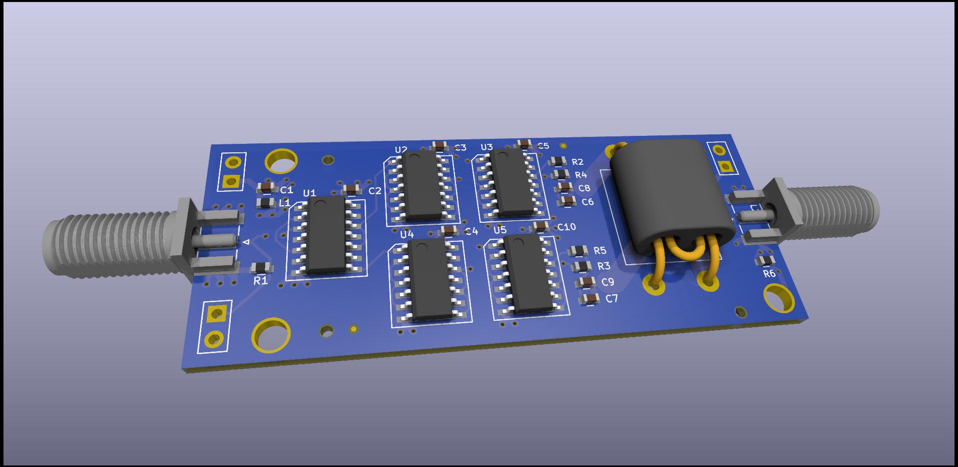
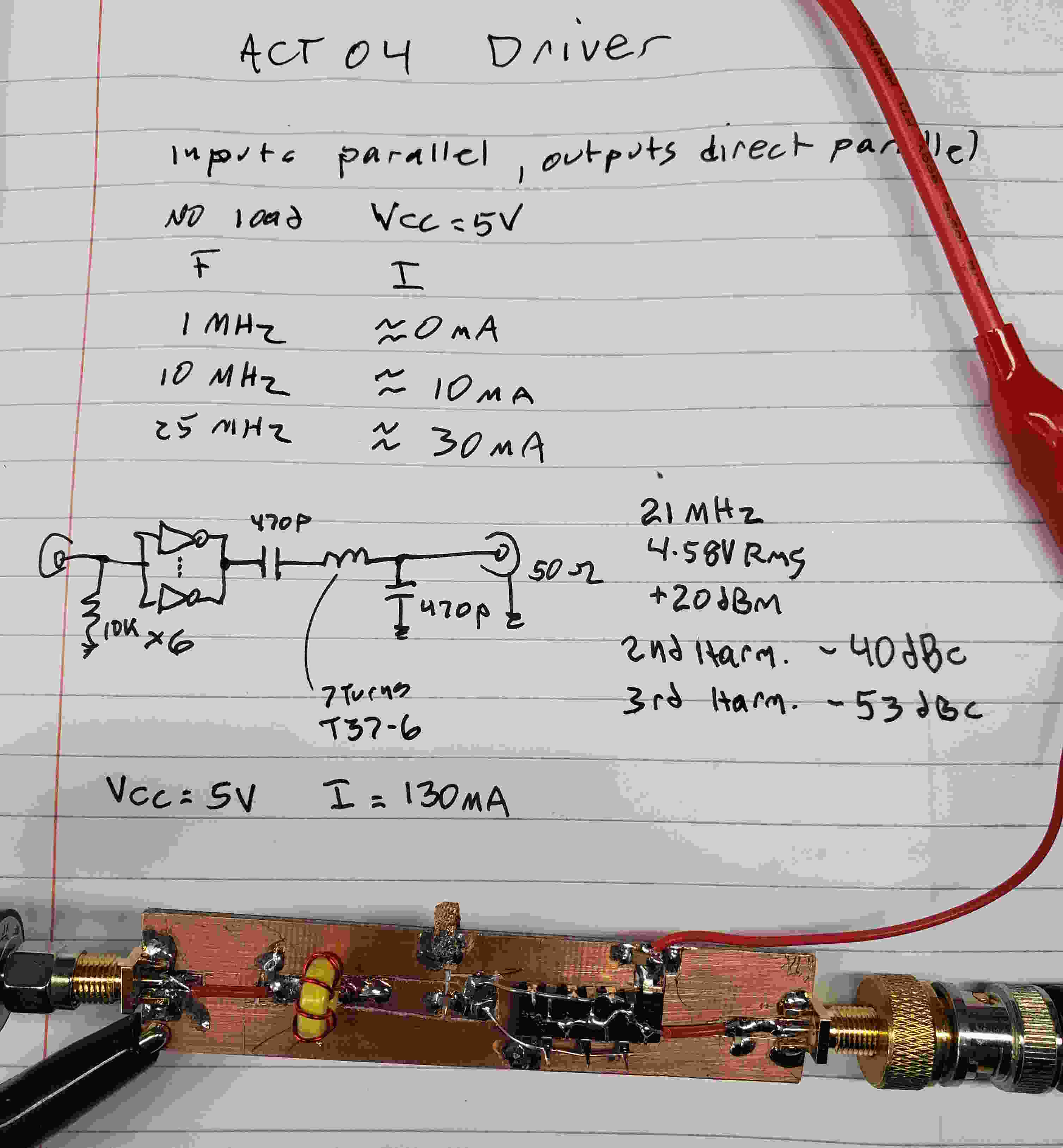
And finally, here’s a 1W (approximately) power amplifier, using 74ACT04 digital integrated circuits to drive a wideband transformer.  This takes a 3.3V digital input between 3 and 30 MHz, and produces a 1W square wave output.  External filtering will be required, and the combiner shown above should provide adequate filtering.

OneWATT v0.1 top

There are “better” ways to make a 1W amplifier, but this is quick and easy, and requires no tuned circuits.  I can’t wait to test these designs!

A Little Amplifier

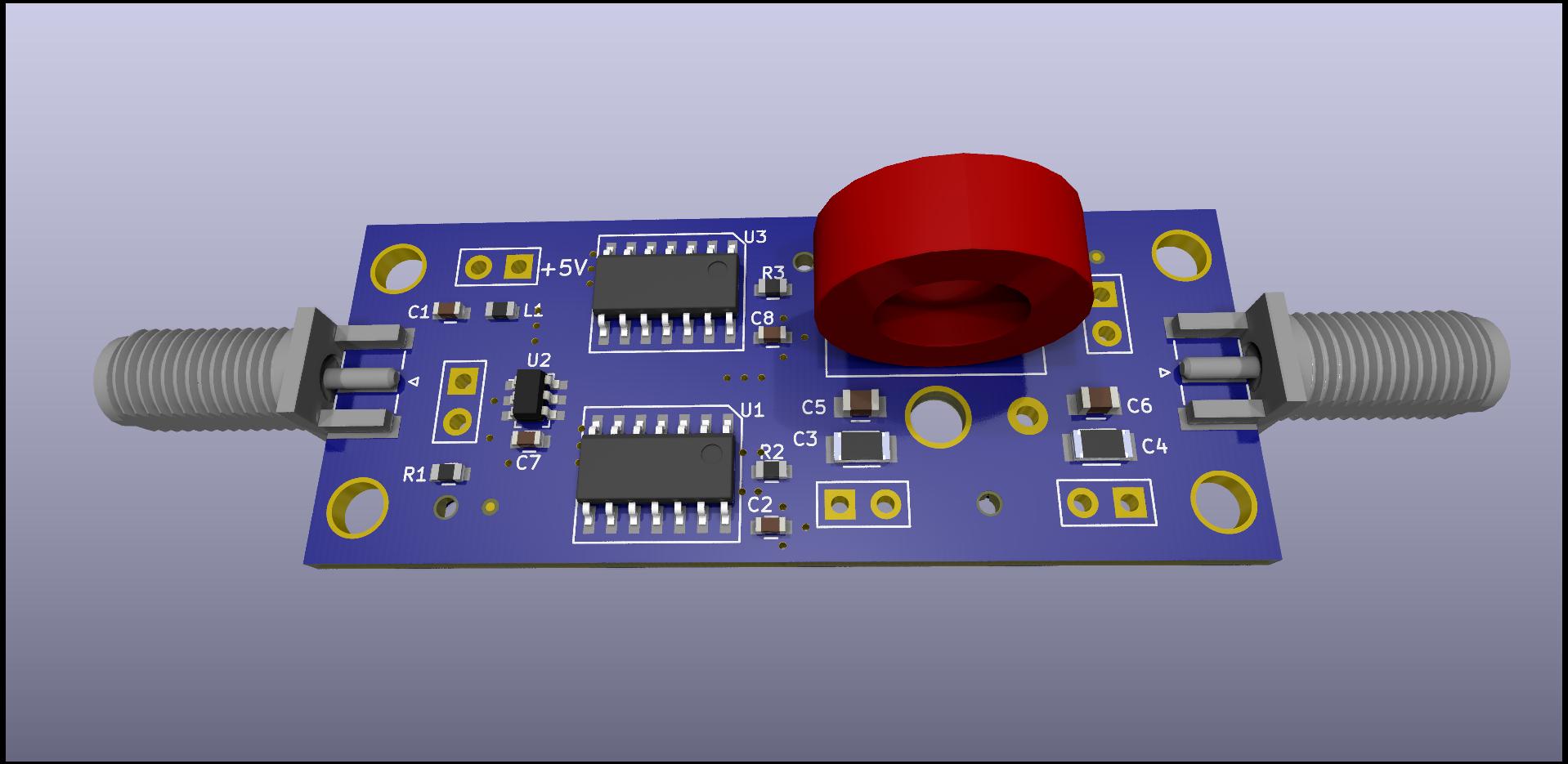
QWATT 0.2 top

In the process of turning my three-output Si5351-based “ClockBox” into a three-band simultaneous FST4W beacon, I decided I needed a small power amplifier to boost the (approximately) 10dBm square-wave outputs up to a 1/4-watt clean sinewave.  Rather than using FETs and transformers, or a Class-E design, I decided to try using the an 74ACT04 hex inverter as the power stage.  Each inverter output can deliver in excess of 25 mA  with about a 4.2V swing (+5V supply) so six of them in parallel looked promising.  And I happened to have a full tube of old 74ACT04 parts in DIP form (remember those?)

So I built one, tuned for the 15 meter ham band:

breadboard 1(Ignore those power-level numbers, I had a bad coax jumper)

I was worried about connecting the outputs directly, afraid that skew would result in excess output-stage current, but some tests showed low unloaded dissipation  up past 30 MHz.  Adding small resistors at each output might be a good tradeoff, but for now I decided not to waste the power.

I used a simple L/C impedance-matching network to transform the 50 Ohm load (antenna) down to about 3 Ohms which matched the ganged inverter output impedance.  Instead of a simple series inductor I used a series L/C, calculated to provide the correct reactance at the design frequency, but giving a high impedance at higher or lower frequencies, and a bit of extra filtering.  This also makes the design slightly more bulletproof — you can run any frequency into it without causing excess dissipation.

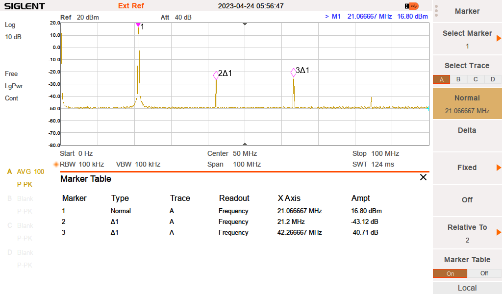
The output power of the test board was actually closer to 1/2 W, and the harmonics were slightly better than 40 dB below the carrier.

PNG2


The amplifier efficiency is about 60% and the temperature rise on the buffer was well within comfortable limits.  This is good enough that I am having some circuit boards made.  The only frequency-sensitive components are two capacitors, and one toroid inductor.  I would have liked to use small surface-mount inductors, and the board does provide for that option, but the toroid has much lower loss.  The board uses two surface-mount 74ACT04 parts, and a small buffer to drive the 12 inverter inputs.

Stabilizing the QDX

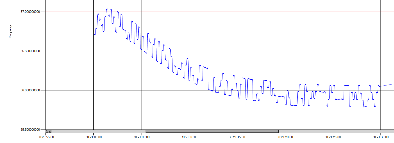
As has been mentioned before, the transmit frequency stability of the QRP Labs QDX transceiver isn’t quite good enough for some of the narrow-band modes.  It works fine for WSPR and FT8, but slower modes such as FST4W-300, -900, and -1800 require stability that the QDX’s internal TCXO just can’t provide.  Here is a plot of a FST4W-1800 transmission, showing the frequency drift as the QDX heats up during the long 30-minute transmit cycle:

FSTW4-1800 30m -v1.6.5 -5

In the plot above, the actual transmit frequency is about 10 MHz, but my measurement system has mixed it down to about 36 Hz in order to get higher measurement resolution.  Add 10.1402 MHz to frequency values shown on the plot.  We can see that the transmit frequency initially rises by about  +0.1 Hz, then eventually falls to -0.85 Hz.

FST4W-1800 has a FSK tone spacing of 0.089 Hz and does not track slow frequency drift, and so requires much better transmit stability than this.  And remember, this test was done in the 10 MHz (30-meter) ham band, the drift will be double that at 20 MHz, and half that at 5 MHz.

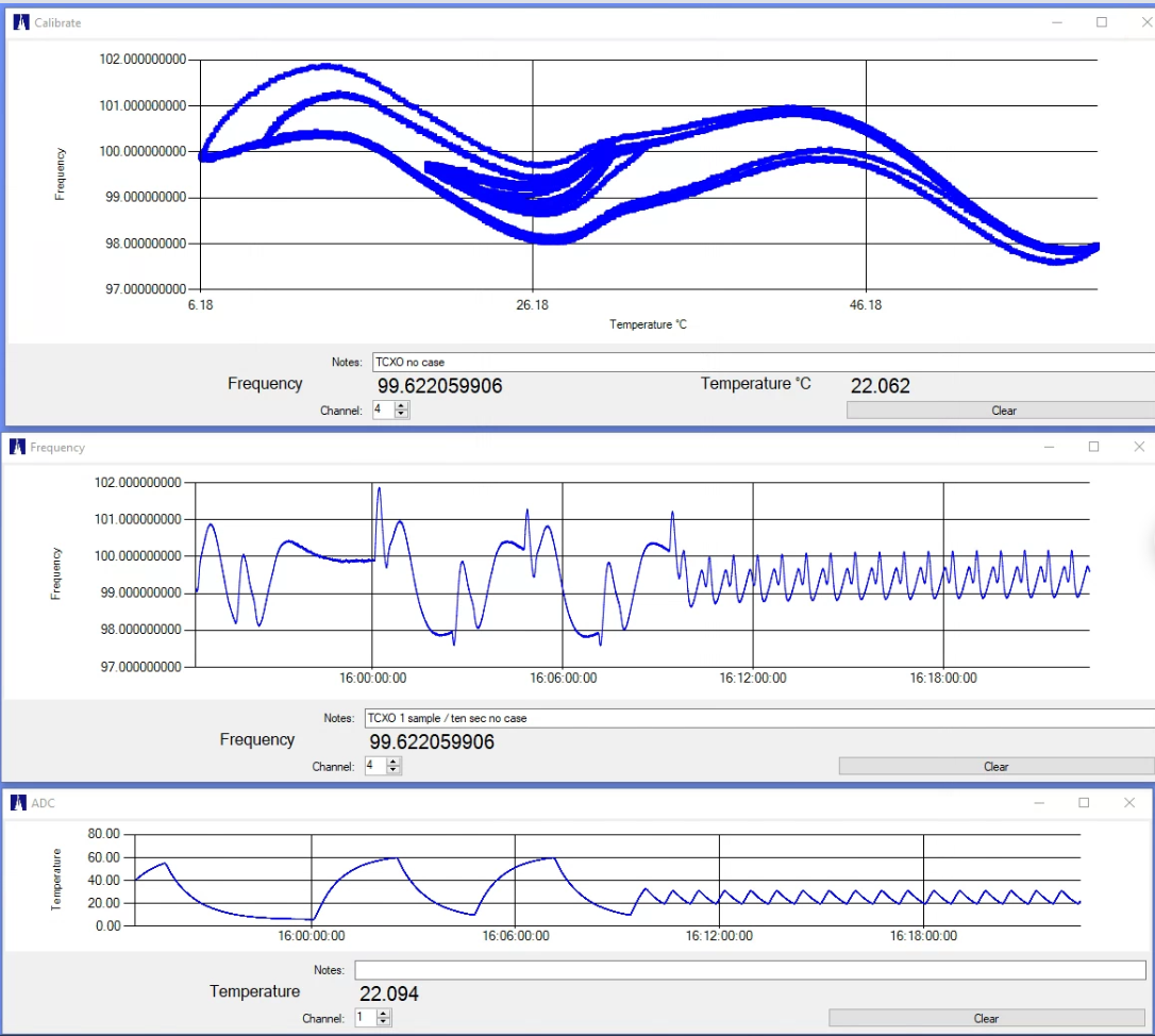
I spent some time looking at the causes and possible solutions for this drift.  First, I ruled out any software issues by measuring the output of the QDX internal 25 MHz TCXO.  Here’s a plot of the TXCO frequency vs ambient temperature, using a homebrew temperature chamber (the QDX was not transmitting during this test):

TCXO - QDX no case-idle 3

The top chart is frequency vs temperature, the middle one is frequency vs time, and the lower one is chamber temperature over time.  Again, here my measurement system is shifting the 25 MHz TCXO frequency down to 100 Hz in order to obtain higher resolution.  We can see that over a 6C to 60C temperature range the TCXO shifts over a range of 4.3 Hz.

We can also see the intriguing phenomenon of “retrace”, where the oscillator frequency exhibits a kind of thermal hysteresis.  All crystal oscillators exhibit this behavior to some extent, and this does limit the amount of correction that can be performed by measuring the temperature (one of the options contemplated for the QDX).

I attempted to slow the rate of frequency change by increasing the thermal mass of the TCXO (attaching a brass tab to the TCXO package), but the results were disappointing — the TCXO is too solidly attached to the circuit board and the heat transferred though the board from the QDX output transistors just couldn’t be escaped.

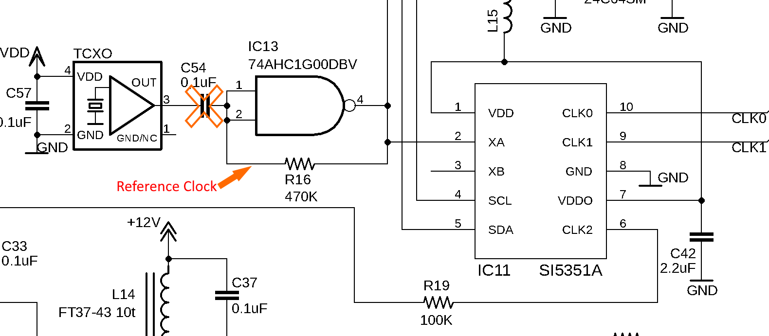
Setting aside any idea of a simple fix, I decided to bypass the TCXO entirely and provide an external clock.  There was room (barely) on the rear QDX faceplate for a SMA jack, and room inside for a small circuit board, do I designed and built a little reference clock multiplier:

schematic

This simple circuit uses a PLL chip to multiply an external reference clock (either 5 or 10 MHz) up to the 25 MHz needed by the QDX.   I will dig into more circuit detail in a later post. This circuit is powered by the QDX internal 3.3V supply, and provides a 0/3.3V logic-level output which is connected to the QDX clock buffer input (after removing the TCXO coupling capacitor):

schem-mod

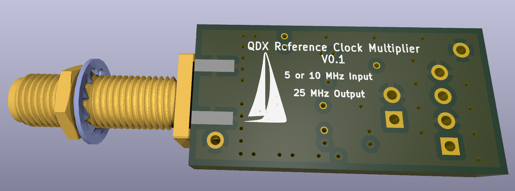
Here’s the little board layout:

PCB

PCB 2

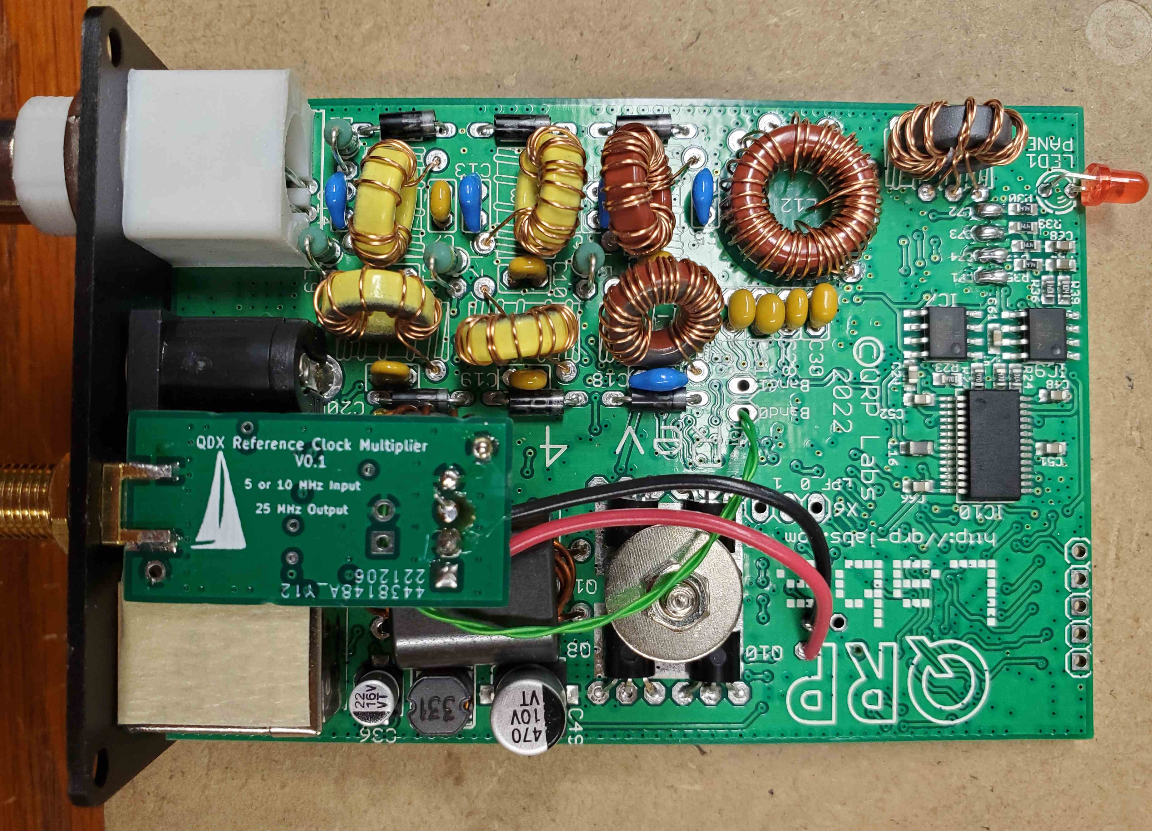
And as installed in the QDX:

RefMult2

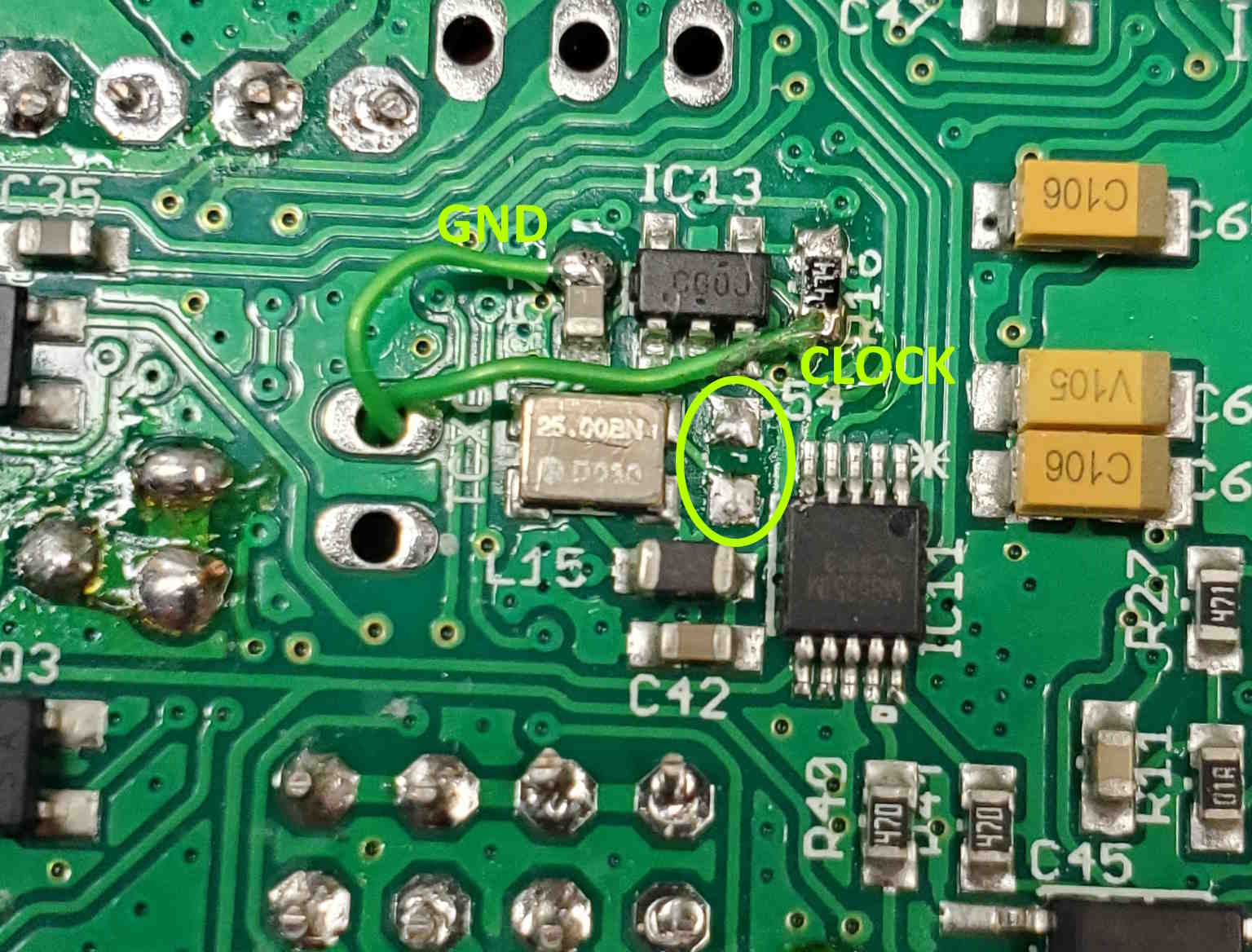
I picked up +3.3V and ground from some testpoints on the QDX board, and having no microscopic coax, I used a twisted pair of #30 Kynar-insulated wirewrap-wire to connect the clock signal to the QDX board (two different-color wires would have made more sense, but I was in a hurry).  The twisted pair just managed to squeeze through another testpoint through-hole, and was then soldered to the PCB:

RefMult3

The yellow oval shows where the TCXO coupling cap (C 54) used to be.

Using a Bodnar GPSDO as my 10 MHz reference I ran some tests.  The 25 MHz output from my PLL was reasonably clean, as was the resulting  signal from the QDX.  Here are some plots of the transmitter, in the 20-meter band:

2

This is a 200 KHz span, 100 Hz resolution bandwidth scan, showing a bit of broadband noise and a discrete spur at -100 KHz (there is another near +100 KHz, not visible in this plot). This noise potentially affects the receiver performance, but initial measurements lead me to believe that other QDX noise sources are dominant.  These measurements only show us the transmit signal, and to determine how much of this output noise is due to the PLL will require further testing. In any case, this noise will have no significant impact on the transmit performance.  We can see how the noise falls off dramatically as we approach the carrier frequency — this is the characteristic of PLL noise under the loop-bandwidth frequency.  Here is a close-in plot:

comparison QDX ext ref

This level of noise is definitely acceptable.

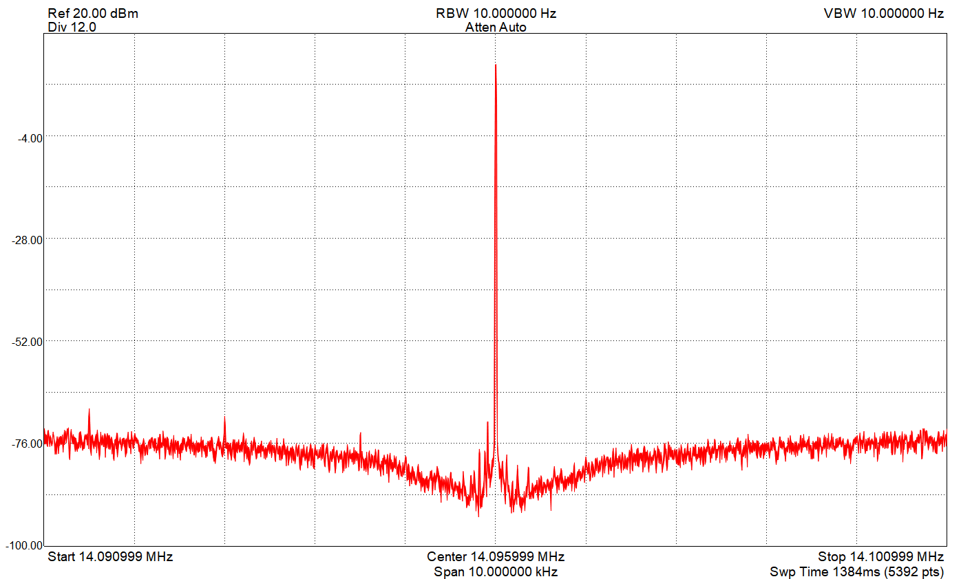
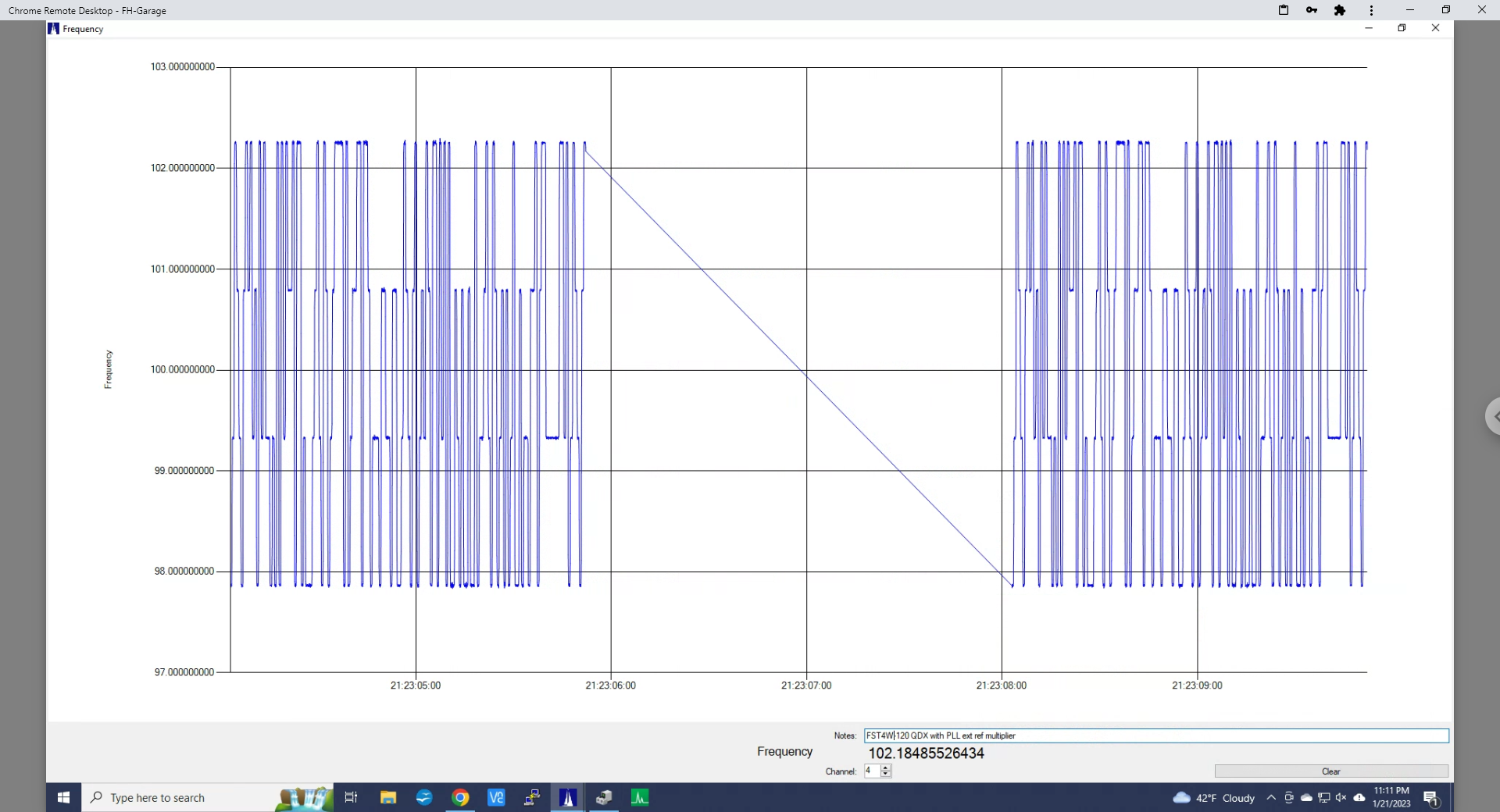
And here are plots showing the transmitted FST4W-120 signal, transmitting on 14.09715 MHz:

FST4W-120 a

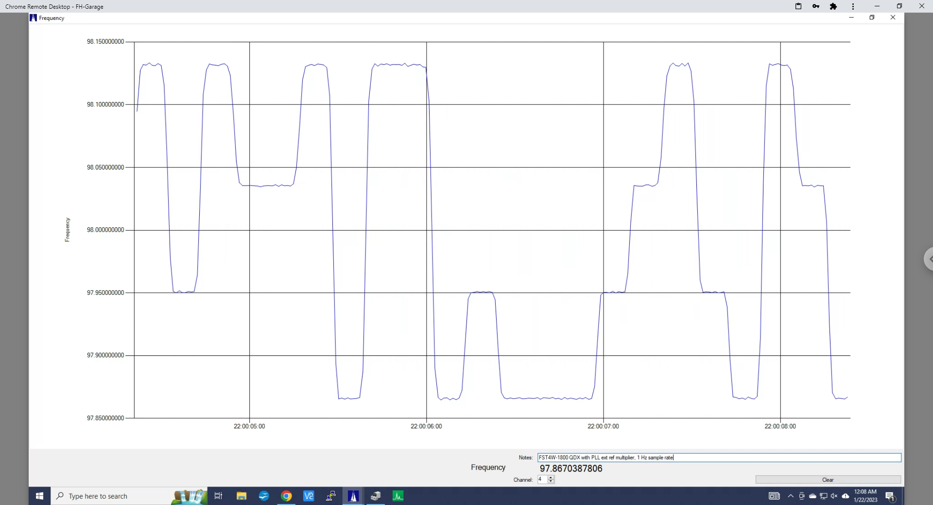
As expected, the transmit frequency is rock-solid.  And here is the modulation in FST4W-1800 mode:

FST4W-1800 b

On-the-air tests of the modified QDX, transmitting FST4W-120 show essentially perfect performance.

About the external reference:

The reference multiplier input can come from any stable source of 5 or 10 MHz.  I tested using a GPSDO, since I distribute that reference to much of my test equipment, but a stand-alone OCXO, or even stable TCXO will serve the purpose.  Obviously, if you already have a stable 25 MHz clock available (the Bodnar GPSDOs can be configured to provide this) you don’t need a clock multiplier — just a connection to the QDX circuit board.  Be sure to provide appropriate coupling and some type of input transient protection!

The 25 MHz clock not only drives the radio portion of the QDX, it also runs the microcontroller.  Without this clock the QDX will not run, and any interruption will likely cause bad things to happen.  The external clock source is the first thing I connect, and the last thing I disconnect.


WSPR With the QDX and QUADRA

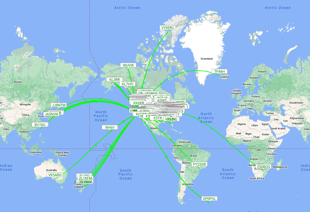
While testing the newest QDX “Beta 1_06_005″ firmware, I hooked it up to the small/cheap inovato QUADRA  linux box and ran some WSPR on 20 meters.  This is what I got after a few hours with 4 Watts into a dipole (I’m currently in California, a bit north of San Francisco):

WSPR 20 metersI’ve always wanted to visit Ellesmere and South Georgia Islands!

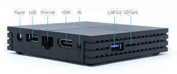
The QUADRA is a nice replacement for the virtually unobtainable Raspberry Pi 3:

quadra