In the process of turning my three-output Si5351-based “ClockBox” into a three-band simultaneous FST4W beacon, I decided I needed a small power amplifier to boost the (approximately) 10dBm square-wave outputs up to a 1/4-watt clean sinewave. Rather than using FETs and transformers, or a Class-E design, I decided to try using the an 74ACT04 hex inverter as the power stage. Each inverter output can deliver in excess of 25 mA with about a 4.2V swing (+5V supply) so six of them in parallel looked promising. And I happened to have a full tube of old 74ACT04 parts in DIP form (remember those?)
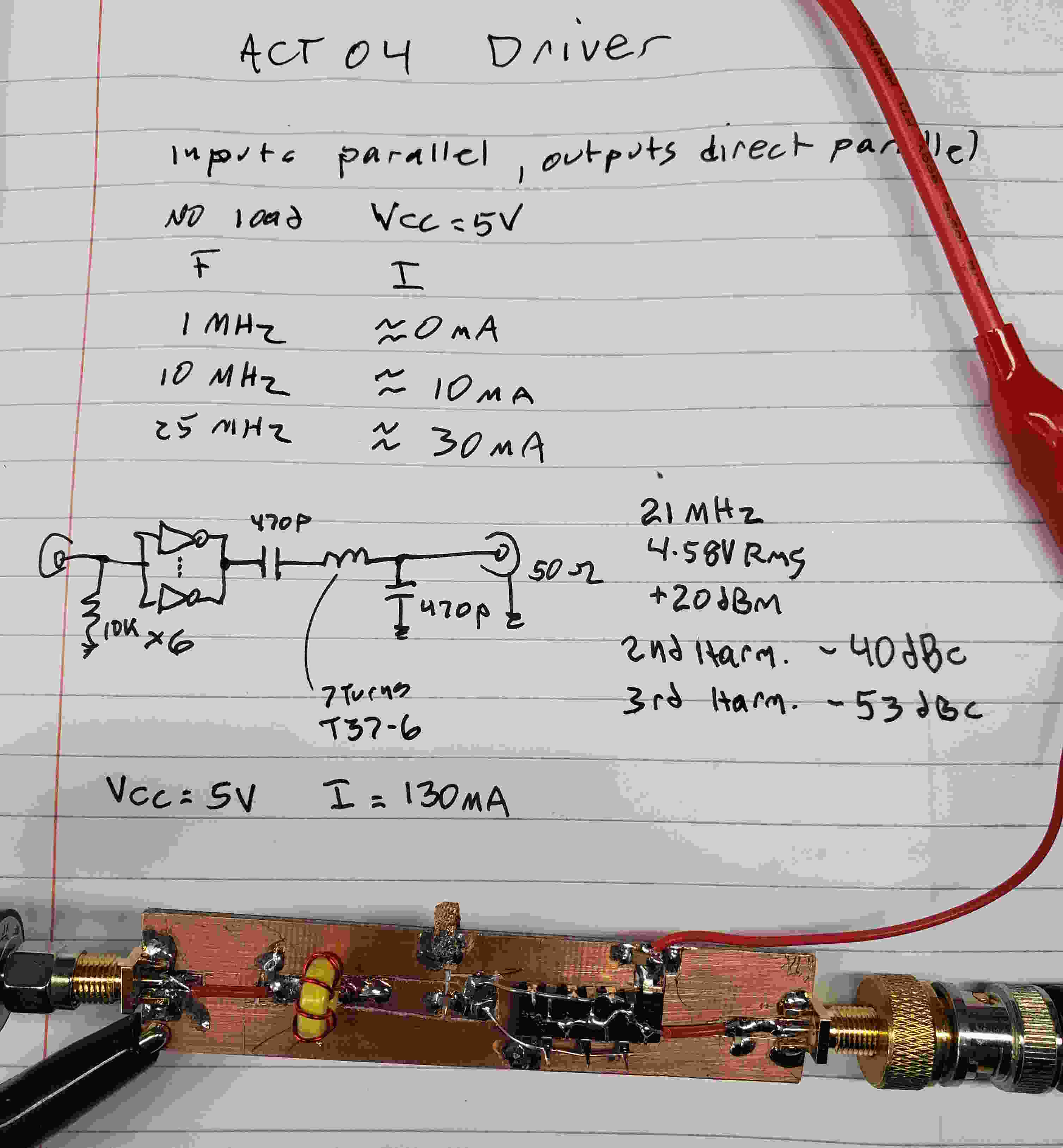
So I built one, tuned for the 15 meter ham band:
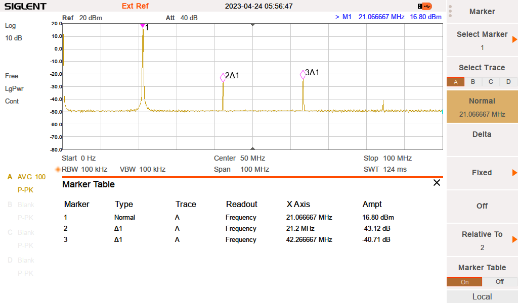
 (Ignore those power-level numbers, I had a bad coax jumper)
I was worried about connecting the outputs directly, afraid that skew would result in excess output-stage current, but some tests showed low unloaded dissipation up past 30 MHz. Adding small resistors at each output might be a good tradeoff, but for now I decided not to waste the power.
I used a simple L/C impedance-matching network to transform the 50 Ohm load (antenna) down to about 3 Ohms which matched the ganged inverter output impedance. Instead of a simple series inductor I used a series L/C, calculated to provide the correct reactance at the design frequency, but giving a high impedance at higher or lower frequencies, and a bit of extra filtering. This also makes the design slightly more bulletproof — you can run any frequency into it without causing excess dissipation.
The output power of the test board was actually closer to 1/2 W, and the harmonics were slightly better than 40 dB below the carrier.
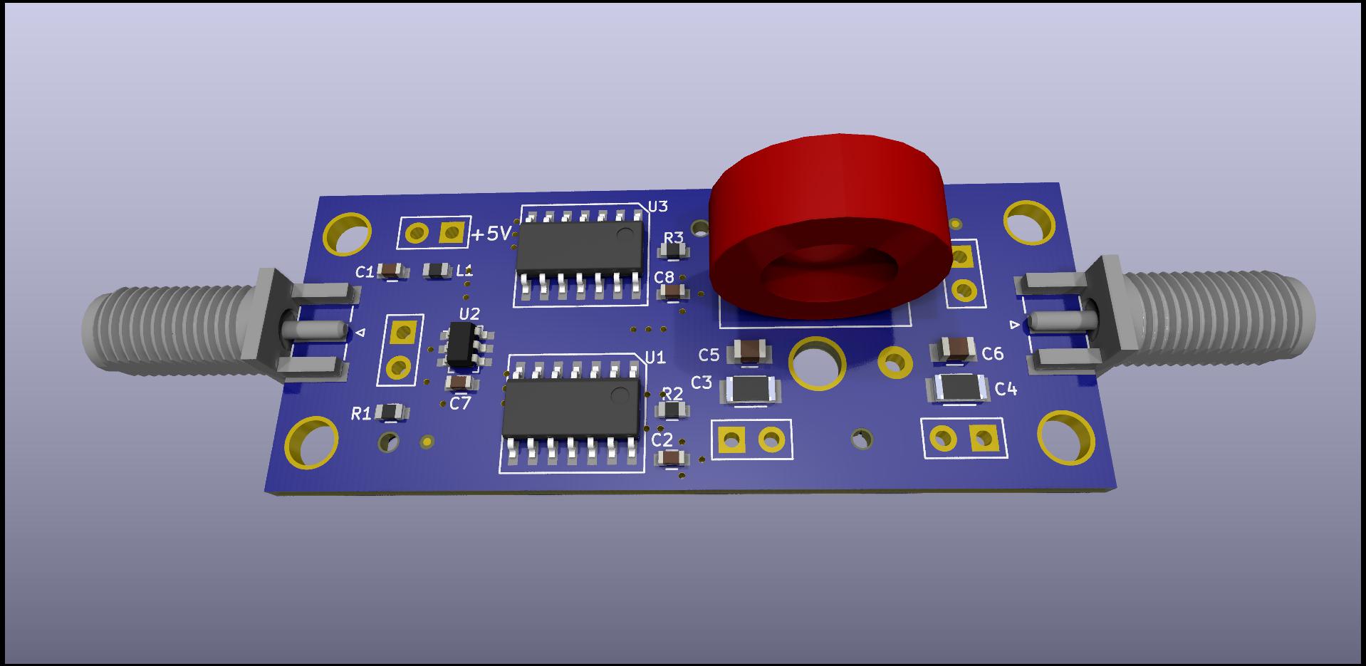
The amplifier efficiency is about 60% and the temperature rise on the buffer was well within comfortable limits. This is good enough that I am having some circuit boards made. The only frequency-sensitive components are two capacitors, and one toroid inductor. I would have liked to use small surface-mount inductors, and the board does provide for that option, but the toroid has much lower loss. The board uses two surface-mount 74ACT04 parts, and a small buffer to drive the 12 inverter inputs.

