As we push the envelope of SDR bandwidth with receivers like the RX-888, In addition to sample rate and aliasing concerns we also also need to look at the dynamic range issues. With traditional “analog” receivers the dynamic range is usually dominated by the IMD (intermodulation distortion) of the front-end preamp and the following mixer stage. Techniques to optimize dynamic range include pre-filtering and AGC (automatic gain control), which can be quite effective when used in relatively narrow-band operation.
But AGC and filtering aren’t so easy in a SDR that is receiving the entire spectrum from (say) 10 KHz to 60 MHz. There is a huge range of signal levels, especially when you are close to a megawatt-level broadcast transmitter. While the 16-bit ADC (analog to digital converter) in the RX-888, with it’s 96dB range, is clearly superior to the 12 and 8-bit ADCs used in many other SDRs, the real-world range of RF signals can easily exceed this.
By the way, the effective dynamic range of an ADC is often several dB better than is suggested by the number of bits, due to what is essentially noise dithering and oversampling.
In some cases the programmable attenuation provided by the SDR can be adjusted dynamically for the best use of the available dynamic range. In addition, there is always the possibility of digital overload and/or digital gain control via numerical scaling within the numerous digital signal processing stages of the software. These are subjects for a different discussion. Here, I’m talking about filters.
While some amount of ADC over-range clipping is tolerable, we usually try to minimize this by inserting attenuation or otherwise setting the gain before the ADC sufficient to avoid significant overloads. We also use a moderate amount of frequency-shaped filtering to reduce input levels at lower frequencies where the general atmospheric noise establishes a higher noise floor. The Turn Island Systems SDR Filter and Filter-Preamp are examples of this type of filtering:
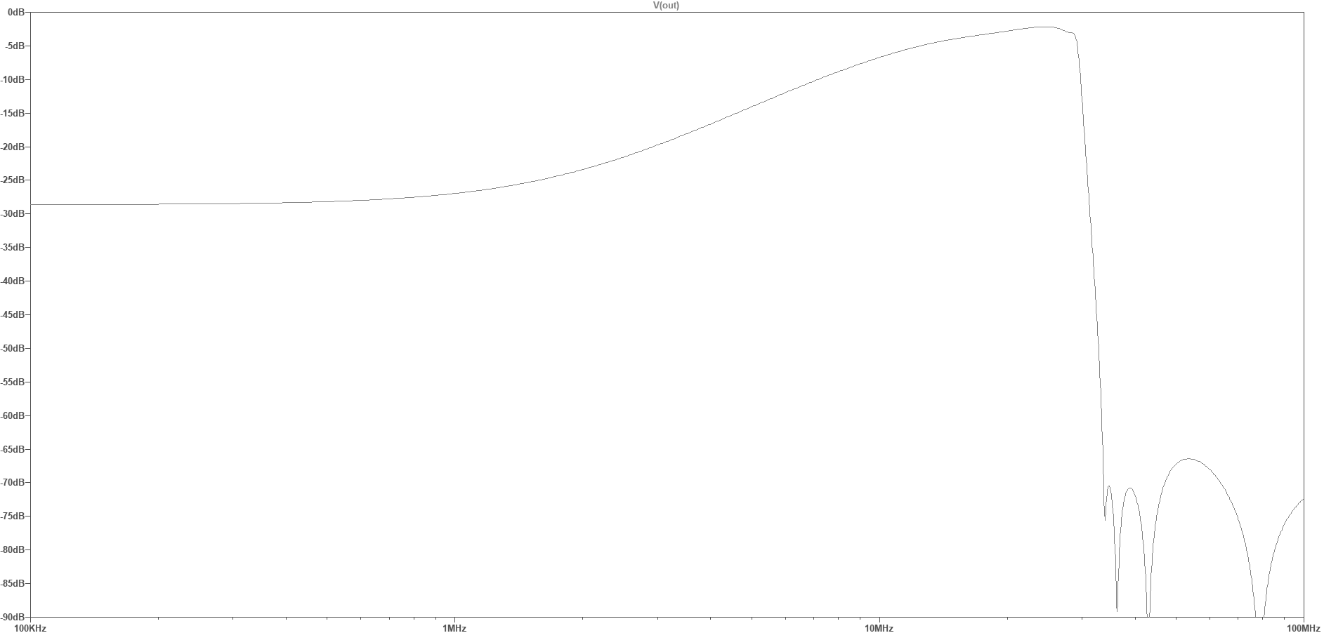
This filter has a steep 30 MHz anti-aliasing low-pass filter, and a high-pass “shelf” filter that attenuates the frequencies below around 10 MHz, flattening out below 1 MHz to a “shelf” attenuation of about 28 dB. This shelf filter roughly compensates for the change in the general atmospheric noise level, and attenuates the USA AM BCB (broadcast band, 540 – 1700 KHz) , helping reduce the chance of ADC overload.
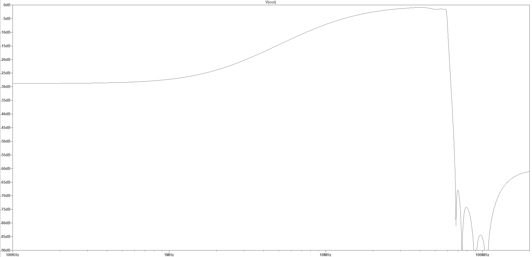
A similar filter/preamp (under development) places the LPF corner frequency at 60 MHz, allowing reception of the 6-meter ham band (requiring a RX-888 SDR sample rate of 130 MHz). This filter also has the stopband notches placed to optimize attenuation of the 88 – 108 MHz FM broadcast band, which would otherwise be aliased down to 22 – 42 MHz in frequency. While the RX-888 does have a built-in 60 MHz LPF, it’s characteristics are pretty marginal (see the links at the end of this post for more details).
While the shelf filter reduces the chance of AM BCB overload, strong signals elsewhere can still cause problems. If these are in the ham bands then simple filtering is not going to help. But some people are using tunable notch-filters to attenuate specific signals, or ham-band bandpass filters to attenuate out-of-band signals. Here is an eight-band bandpass filter I am currently working on (I’m calling it the BPF8):
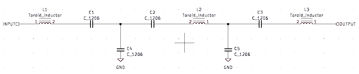
The BPF8 is actually a bank of three-section bandpass filters connected in parallel. Each filter has this design:
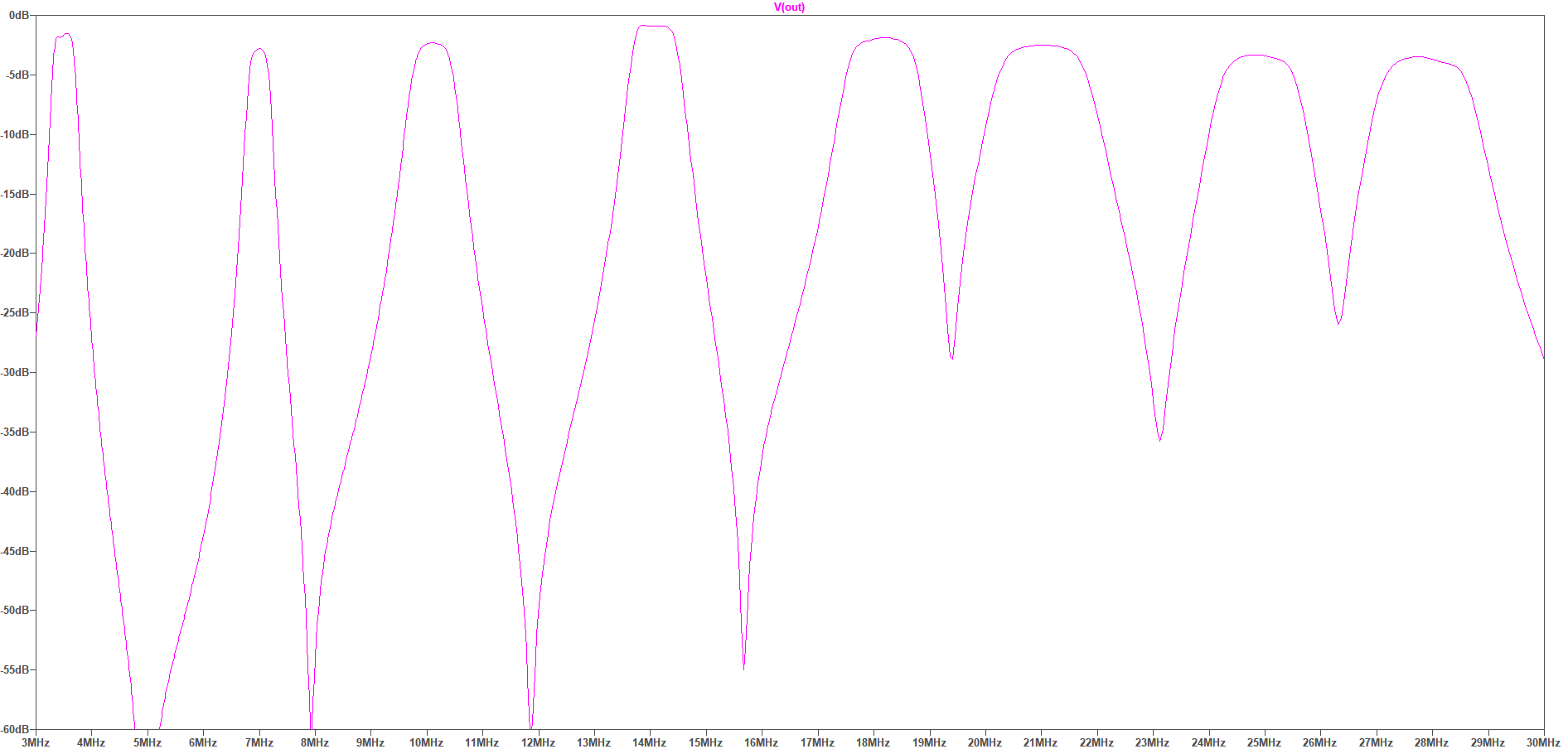
The (simulated) overall response looks like this, covering the 80, 40, 30, 20, 18, 15, 12, and 10 meter ham bands. These filters are tuned for the WSPR sub-bands:
Will this help with SDR dynamic range? That depends on the interference — if the out of band signals aren’t strong enough to create problems then this filter will be unnecessary.
If reception between the filter bands is still desired, a broadband shelf response can be selected (via a jumper), which limits the maximum attenuation — here, to 30 dB:
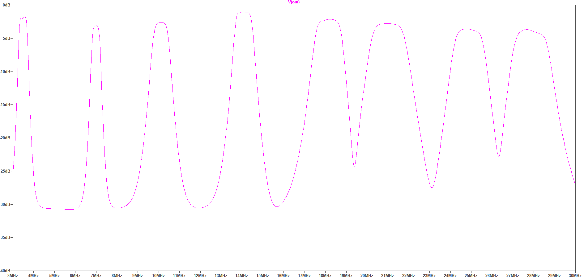
In the USA, most of the BCB signals are below that 1700 KHz frequency. But in Europe there are many powerful broadcast transmitters scattered over the HF frequencies, and these can cause big dynamic range problems. Here are the shortwave BCB frequency bands superimposed on the above multiband filter response (some of these bands are only lightly or regionally in use):
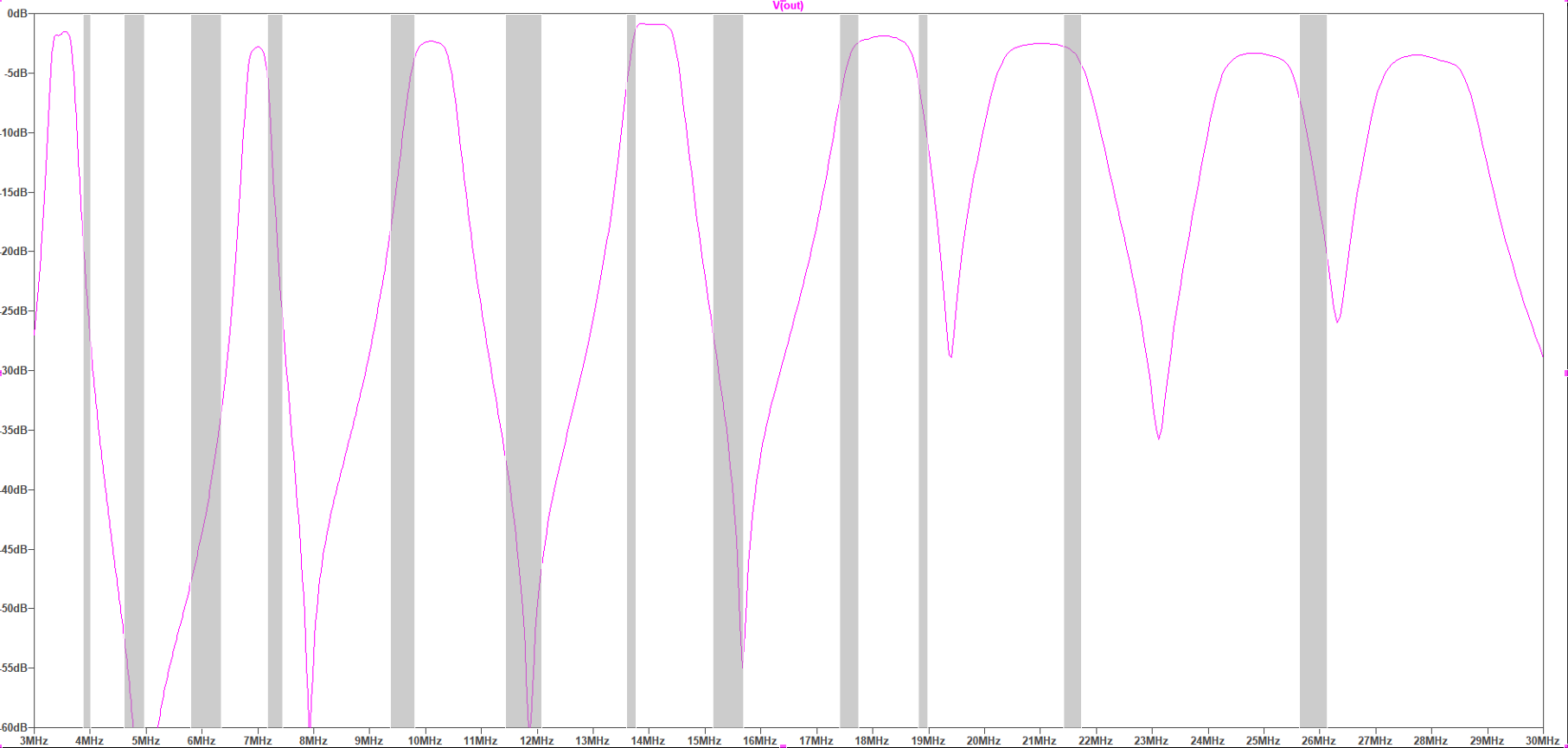
As you can see, some of these SW BCB frequencies are extremely close to the ham bands, and so in those cases the filter will probably not help much, while other SW BCB signals will be significantly attenuated. The BPF8 will probably include jumper options to optionally disable a selected filter section. Is the BPF8 worth a try? We shall see.
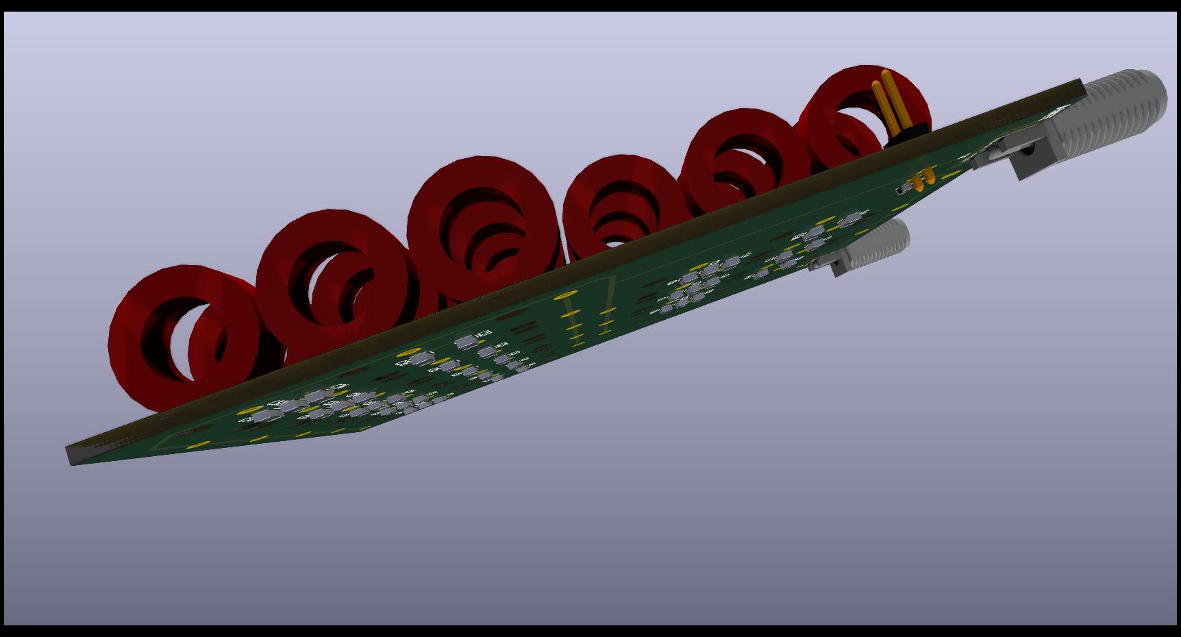
The BPF8 prototype board is densely populated with 24 toroid core inductors, used for their low-loss and self-shielding characteristics. The filter capacitors are on the underside of the board. This will be another “hard to build” design, because of all the hand-wound and tuned toroids, but I hope the results will be worth it.
For more details of the RX-888, and about shelf filters, look at KA7OEI’s blog for some excellent in-depth discussion of these issues:
measuring-signal-dynamics-of-rx-888-mk2
revisiting-limited-attenuation-high-pass-filter
International broadcast bands:
International_broadcast_bands (Wikipedia)