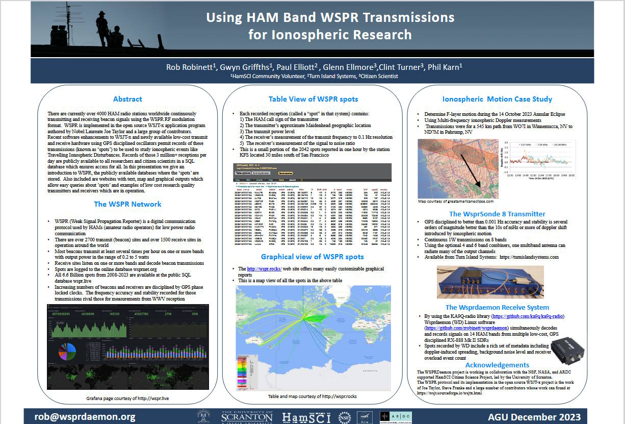
As you may know, over at Turn Island Systems (TIS) we have developed the WSPRSONDE-8 (WS-8), a multi-channel transmitter used in ionospheric propagation measurements. This transmitter has eight channels, each covering 160 to 6 meters (and all frequencies in-between), each channel capable of transmitting at the same time. Typically some or all of these outputs are combined to feed a single multi-band antenna, using one of the TIS filter-combiner boxes. The WS-8 and earlier incarnations are currently transmitting at locations on multiple continents, in support of the HamSci ionospheric study programs.
TIS has a test site near Occidental, California where I have a number of antennas and now two WS-8 transmitters. One antenna is the EFHW-8010 from myantennas.com, and this is being driven by one WS-8 through a prototype nine-band Filter-Combiner. The frequencies are 80/40/30/20/17/15/12/10 meters.
The second WS-8 is driving two dipoles, one for 160 meters, and the other for 6 meters.
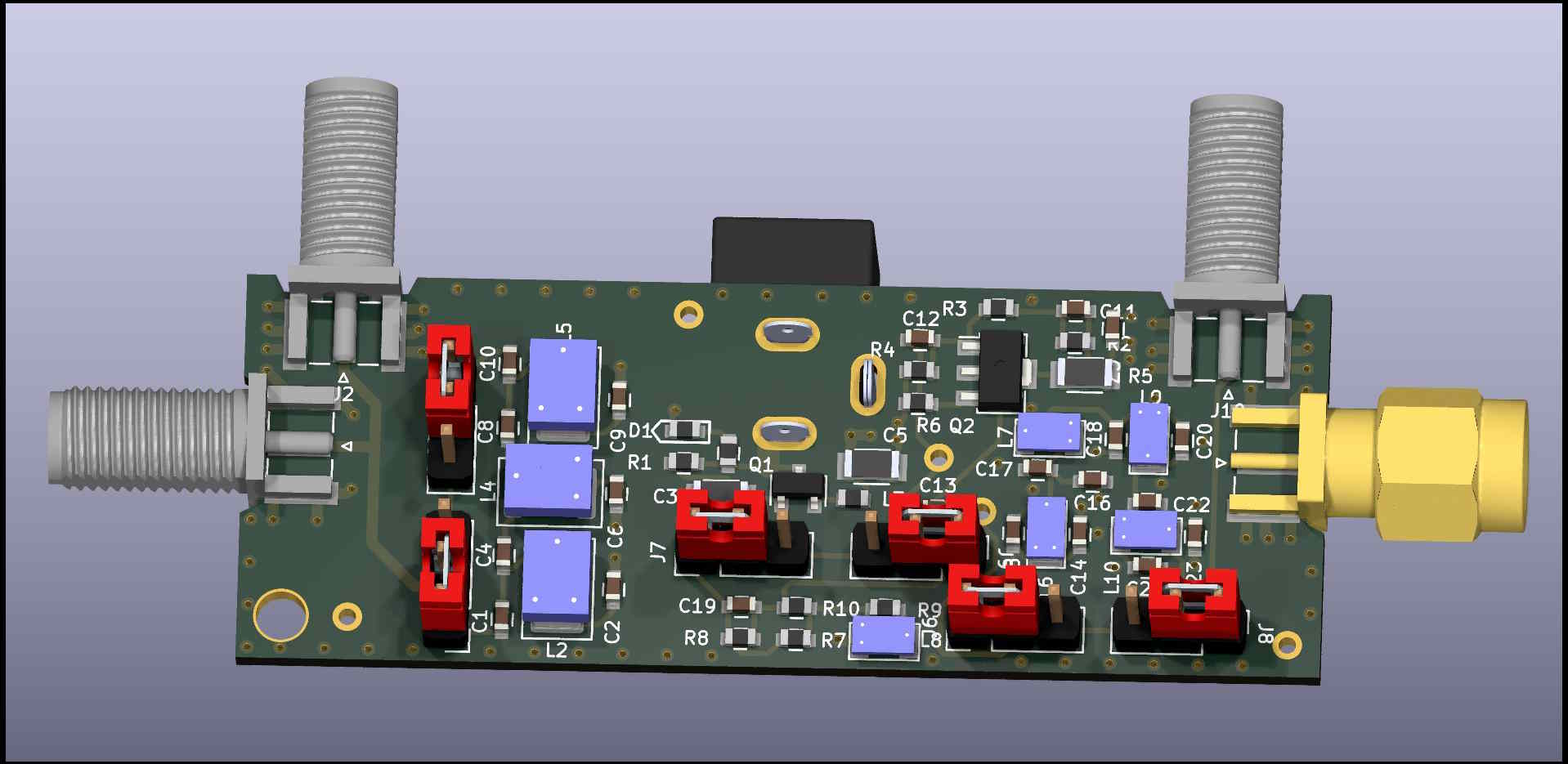
Here is the new setup: 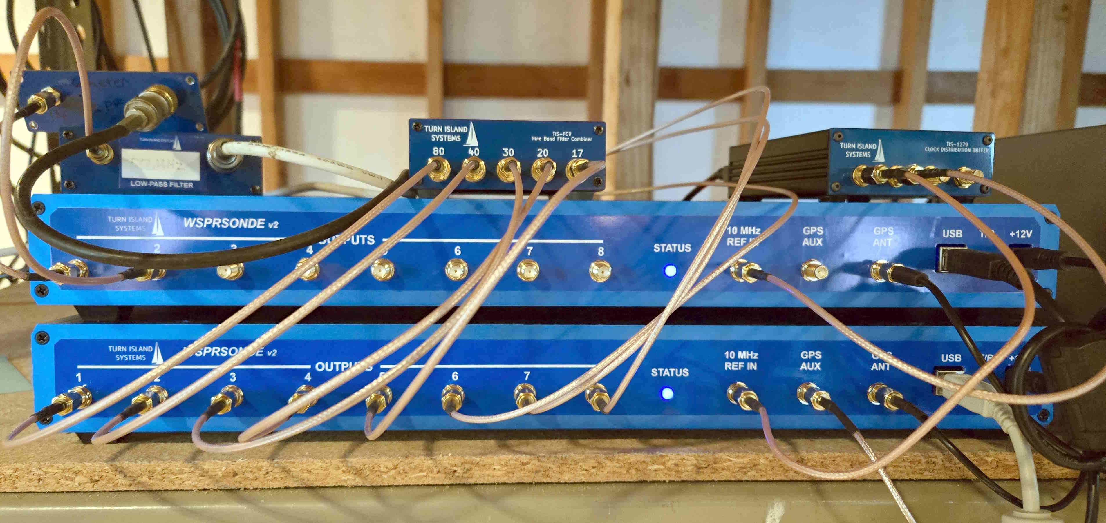
The little boxes on top of the WS-8 stack are (left to right):
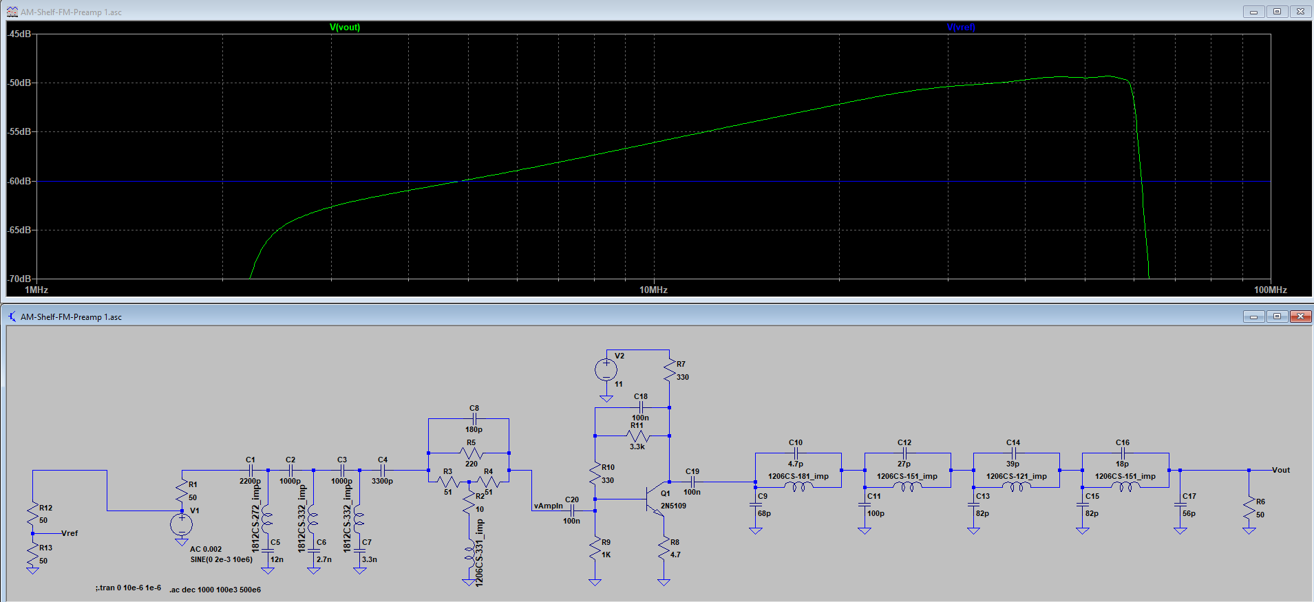
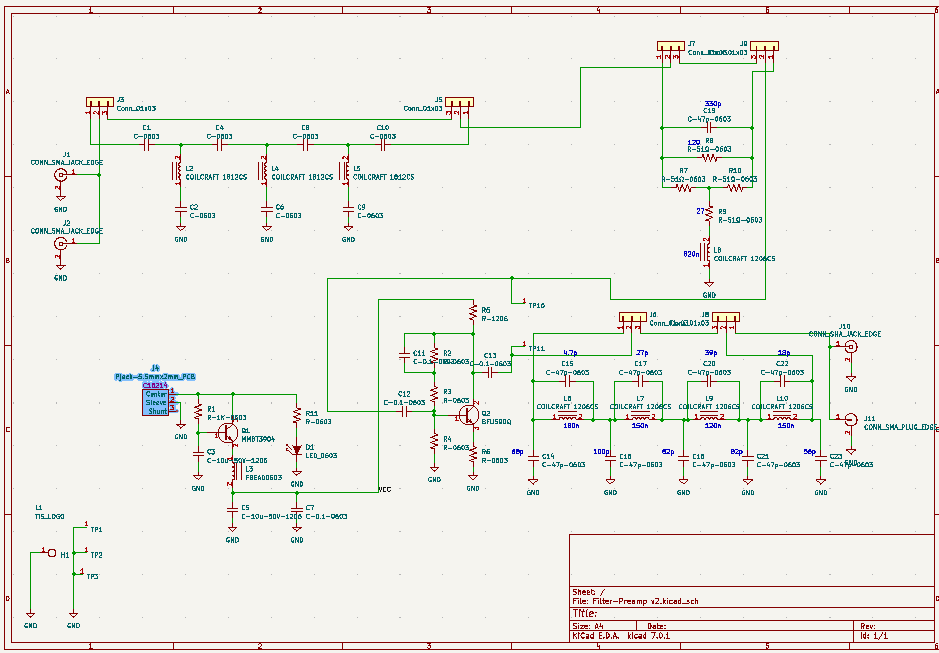
- 160 meter Low Pass filter — This is a L/C/L/C filter, with a few dB of peaking. I used T50-2 toroids for the inductors. The input series inductor reduces the loading on the WS8 power amplifier (the strong third harmonic sees a rather high impedance). Harmonic suppression is better than -50 dBc.
- 6 meter Low Pass Filter. This is a simple L/C/L TEE filter, again using toroids (T50-6).
- 9-Band Filter-Combiner. There is a description of this on the Turn Island Systems website.
- Clock Distribution Buffer (a predecessor to the TIS-126). This is taking the output of a Bodnar GPSDO and sending it to the two WS8 units.
If you care to listen to these transmitters, here are the frequencies (“tone 0″ of the FST4W 4FSK):
WS8 #1 (EFHW-8010):
Channel 1, frequency: 3,570,135.000000 Hz
Channel 2, frequency: 7,040,134.926829 Hz
Channel 3, frequency: 10,140,234.959350 Hz
Channel 4, frequency: 14,097,134.959350 Hz
Channel 5, frequency: 18,106,134.878049 Hz
Channel 6, frequency: 21,096,134.878049 Hz
Channel 7, frequency: 24,926,134.869041 Hz
Channel 8, frequency: 28,126,134.634146 Hz

WS8 #2:
Channel 1, frequency: 1,838,134.982578 Hz
Channel 2, frequency: 50,294,534.290017 Hz