I noticed something interesting when I was testing my Raspberry Pi WSPR transmitter: just how littlesignal is needed to receive WSPR! I was using a FUNcube Dongle Pro+ receiver to monitor my transmitted signal. This neat SDR (Software Defined Radio) covers from 150 KHz to 1.9 GHz (with a gap between 240 and 420 MHz). It has some nice built-in filters and performs well.
FUNcube Dongle Pro +
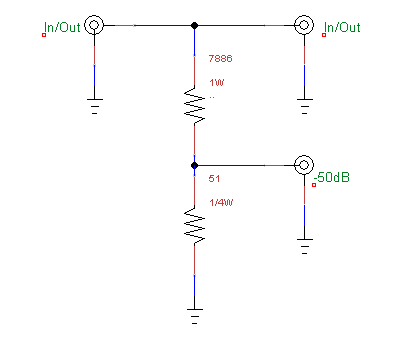
The FUNcube was feeding the WSPR WSJT-X program (WSJT-X), and connected to the RPi WSPR transmitter / antenna with a -50dB tap/attenuator:
-50dB tap / attenuator
I made this attenuator a while back when I was testing my 100-Watt ham HF transceiver. This tap lets me connect the rig to a dummy load (or an antenna) and siphons off a low-level signal that I can connect to my spectrum analyzer or other measuring equipment. With a 100W through-signal, the signal at the tap is 1mW (that’s -50dB). With that 100W signal the 7886 Ohm resistor dissipates about 0.6W, so I paralleled four 1/4W resistors (3300 || 3300 || 3300 || 2700 Ohms) to get close to the calculated value. The thing works well enough at HF frequencies, but I wouldn’t trust the accuracy at VHF.
Anyway, with this tap I could monitor my on-the-air 20-meter WSPR transmissions. What really surprised me was when I started receiving WSPR signals from the K6SRO WSPR beacon through that 50dB attenuator! K6SRO transmits at 5W at a distance of over 1,000 kilometers from my receiver. The received signal-to-noise ratio was -17dB, which is at least 12dB better than needed for WSPR decoding.
I suppose this reminds us that on the HF bands the atmospheric background noise is usually the dominant factor, and when it comes to receiving our antennas are less critical that we might imagine.
I was fairly astounded to see the difference in spurious signal generation between the two versions of the WsprryPi . Here’s the output from https://github.com/8cH9azbsFifZ/WsprryPi:
What caused the reduction in spurious outputs? I’ve been studying the programs, and while I still haven’t figured out a lot of the details, one significant difference is the addition of this bit of code:
while (n_pwmclk_transmitted<n_pwmclk_per_sym) {
// Number of PWM clocks for this iteration
long int n_pwmclk=PWM_CLOCKS_PER_ITER_NOMINAL; // Iterations may produce spurs around the main peak based on the iteration // frequency. Randomize the iteration period so as to spread this peak // around. n_pwmclk+=round((rand()/((double)RAND_MAX+1.0)-.5)*n_pwmclk)*1;
if (n_pwmclk_transmitted+n_pwmclk>n_pwmclk_per_sym) {
n_pwmclk=n_pwmclk_per_sym-n_pwmclk_transmitted;
}
There may be other relevant changes to the code, but this looks like the big one when it comes to output spur generation. I will play with it, as well as digging into the rest of the code, and report back.
[Updated Dec 25 -- corrections and clarifications] WSPR is the ham radio “Weak Signal Propagation Reporter” system (http://wsprnet.org/). Here is my recent experience using a Raspberry Pi as a very simple stand-alone WSPR transmitter.
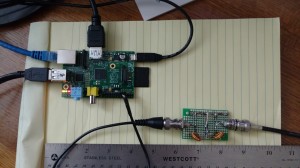
Shown above is a Raspberry Pi Model B, going through a four-pole 14MHz bandpass filter, and then to a multiband dipole strung through the trees. It transmits on approximately 14.0971 MHz, at a power of +10 dBm (0.01 Watt).
Raspberry Pi Versions and code compatability
There are several Raspberry Pi versions. I first tried using my new Raspberry Pi B+
Raspberry Pi 2 Model B+
I used this code: https://github.com/8cH9azbsFifZ/WsprryPi, which had been referenced by several people who had used the RPi for WSPR. It didn’t work on this version of the Raspberry Pi, and by inserting debugging “printf” statements could see that it was getting hung up when using DMA (a type of memory access). A bit of Googling found that this was a known problem, but the program would run on the older RPi. I tried it on my older Raspberry Pi-B, and it worked!
Raspberry Pi Model B
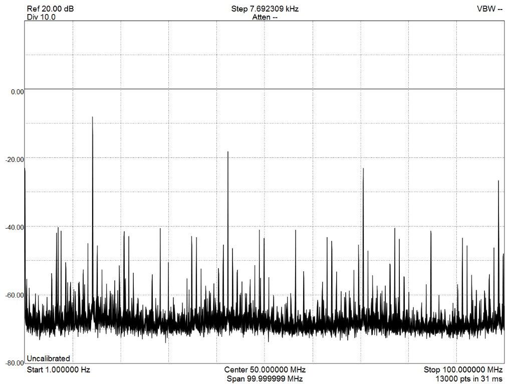
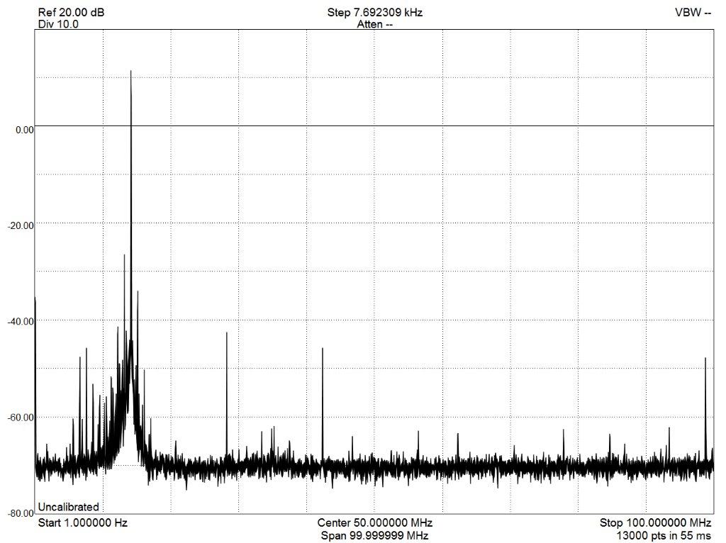
Here is the raw Pi output between 0-100 MHz :
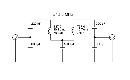
I used a capacitively-coupled -20dB pad for this measurement. You don’t want to put a resistive 50-Ohm load on the RPi output, so I used a 0.1uF DC-blocking capacitor. Notice all the spurs being generated by the Raspberry Pi. We see the typical strong odd-harmonics that we would expect from the squarewave output of the Pi, and weaker even-order harmonics since the output isn’t a pure squarewave (rise and fall times probably aren’t identical.) There are also other spurious signals, -32dBc (dB below the carrier). These are presumably sampling artifacts, caused because we are effectively sampling a 14 MHz squarewave with the internally-generated 250 MHz clock driving the Pi divider. More on this later… So the RPi output is a bit too dirty to put on the air. I’ve seen people use a Pi-network low-pass filter for this, but because there are lower-frequency spurs as well as harmonics, I decided to use a simple band-pass filter:
14 MHz Bandpass Filter
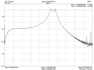
Note that the inductor values are calculated, not measured. I wound them using #28 enameled wire on a T37-6 toroid core from Amidon. This filter has a capacitive divider input and output so there is no issue with DC loading the RPi output. Here is the filter response:
I have it a bit overcoupled to simplify tuning, so I lose a few dB at the 14.0971 MHz operating frequency. If I get ambitious I might optimize it, but it works well enough for now. Here is the RPi output after the filter:
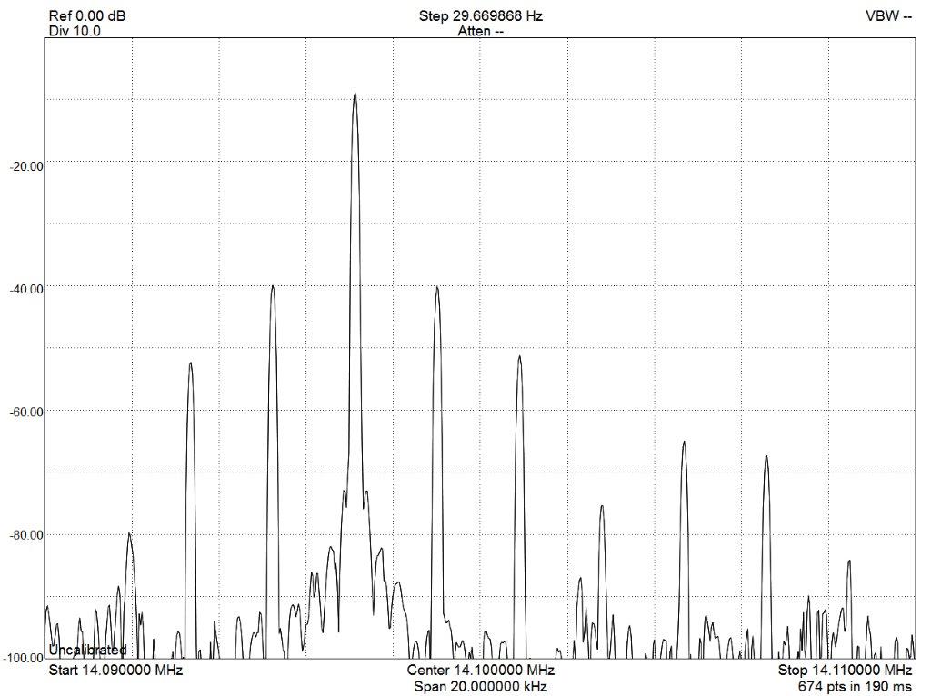
You can see that there are still some close-in spurs that my simple filter isn’t going to take care of:
Still, the spurs are about 30dB below the 10mw carrier, so I decided it was good enough and put it on the air.
But what about the Raspberry Pi 2 B+???
This code still wouldn’t run on the newer RPi 2 B+. After a bit of searching I found this code update which had fixed the hardware dependencies that broke things on the new Pi: https://github.com/JamesP6000/WsprryPi In addition, this version has more command-line options that are very useful for debugging and running WSPR. I tried it first on the older RPi-B.
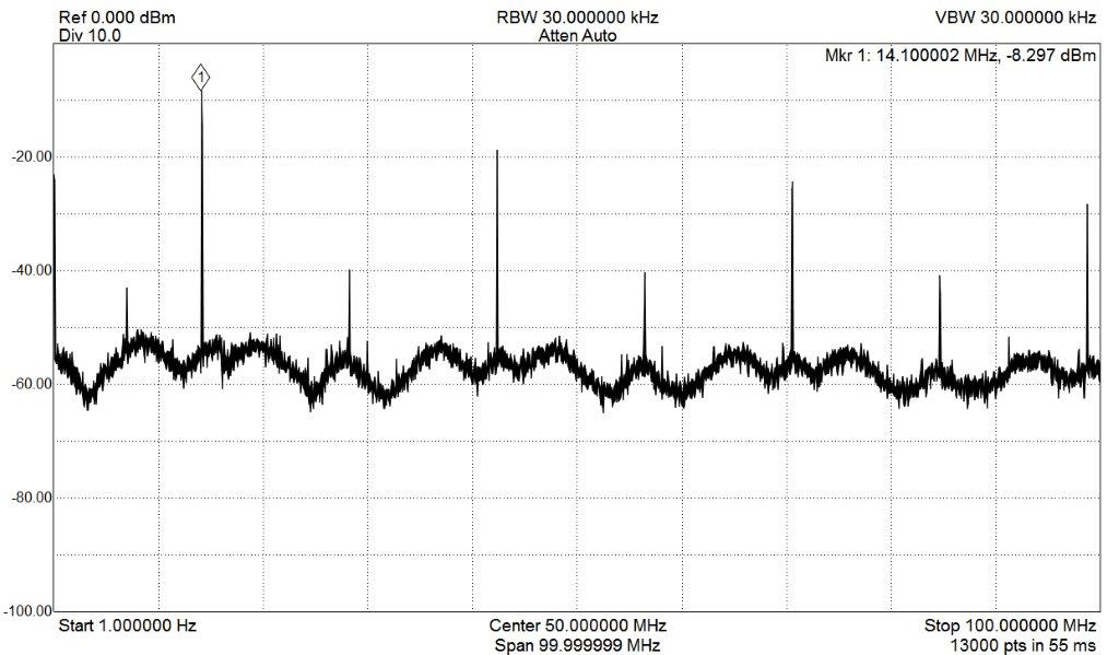
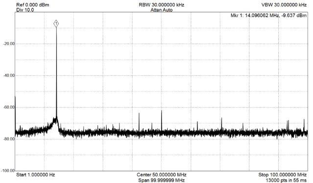
WOW! What happened to the spurs???
The output was dramatically different with this new code. Look below and notice how most of the non-harmonic spurious signals have disappeared! We now have the fundamental, strong odd harmonics, weaker even harmonics, a few (presumably) sampling artifacts, and a wideband, low-level noise floor around -50dBc (I used a peak-hold setting to capture the worst-case noise-floor envelope):
Running it through my band-pass filter we get a really nice signal:
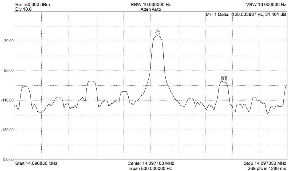
Zooming in we see a very clean carrier with just a hint of close-in noise:
Zooming in further we see what look like 60 and 120 Hz sidebands, presumably coming from the cheap wall-wart USB charger I am using to power the RPi.
Why does this new code generate a cleaner output, seeing that the hardware is identical? I need to compare the two versions, but I suspect that the difference is in the choice of divisors and the configuration of the MASH noise-shaping. Here’s a link to the RPi divider hardware that covers some of the details of operation (see section 6.3): https://www.raspberrypi.org/wp-content/uploads/2012/02/BCM2835-ARM-Peripherals.pdf
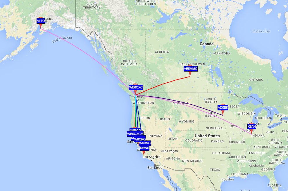
I will report back in a few weeks when I get a chance to dig further into this. I haven’t even tried this on the new RPi 2 B+, but I will soon. Until then, the RPi WSPR transmitter is running full-time from my Friday Harbor location: The signal was being received so well by some friends in Sonoma County that I put the 20dB attenuator back in between the Pi and the filter, reducing the output to -10dBm (100 micro-Watts). The signal was still received at a distance of 1121 km, giving us about 11 million kilometers per Watt! I have since resumed transmitting at +10dBm.
10mW WSPR on 20 meters
More details to come: I will be writing about these topics sooner or later:
Links to other WSPR / Pi articles
Frequency stability with the tiny low-cost Raspberry Pi oscillator
WSPR timing accuracy using Network Time Server
GPS time and frequency (?) synchronization
Hardware connections
Remote control of Raspberry Pi over the internet
Operation on other frequencies
Analysis of Raspberry Pi frequency generation, especially spectral purity and noise-shaping