While evaluating the behavior of the QRP Labs QDX transceiver (my post here: http://wb6cxc.com/?p=244 ), I put together an old-fashioned mixer / filter to let me make more accurate FSK frequency measurements. I am using my Time Interval Counter, which counts the cycles of a 100 MHz (10 ns) internal timebase, and calculates the frequency of the input signal using simple math:
Frequency = 1 / Period
This works especially well for lower frequencies, where obtaining precise frequency results with a standard cycle-count counter requires extremely long measurement intervals. The resolution of a reciprocal counter is a function of the timebase, in this case the 10ns timebase provides eight digits of precision with a one-second count interval (10ns / 1s = 1e-8)
Eight digits is good, but when measuring 10.140 MHz WSPR, with its symbol rate of 1.4648 Hz we need to do better. With three samples per symbol (about the slowest we can sample it), we only have (10ns/ 0.5s), or about 7.5 digits. This lets us measure a 10.140 MHz signal to about 1/2 Hz resolution. This will show us the presence of the modulation, but not much more:
Using an external mixer and VFO to shift the 10 MHz signal down to 100 Hz makes a huge difference in measurement resolution. With our 1/2 second sample rate we still have 7.5 digits of resolution, but since we a re measuring a 100 Hz signal the resolution is now about 0.00005 Hz!
But I don’t need an external mixer and VFO — all that can be done digitally inside the gate-array I use on my frequency counter:
So I added those to the FPGA logic: 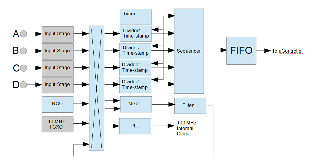
This is the block diagram of the signal path in the counter. The blue boxes are contained in the gate-array, and the grey boxes are discrete components on the circuit board. Not shown are the uController, and a few other sections inside the gate-array.
There are four input stages, configurable for 50-Ohm or High-Z input (compatible with a 10X ‘scope probe), AC or DC coupled. Each stage, the NCO, the 10 MHz TCXO, and a few other sources (not shown) feed a N-way selector that feeds four divider/timestamp blocks. The switch also allows any of the input ports to feed a 10 MHz reference clock to the internal 100 MHz PLL. This allows the counter to use an external OCXO or GPS-disciplined oscillator for increased precision. In addition, the switch selects the mixer inputs.
The NCO is driven by the 100 MHz clock, and is 29-bits wide. This provides a frequency resolution of 100 MHz / 2e29, or 0.186xxx Hz, and a maximum frequency of 50 MHz. The 100 MHz clock means there will be a jitter of 10ns in the NCO frequency.
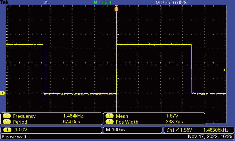
The NCO or an external signal drives the “clock” of a simple flip-flop mixer, and the external signal feeds the “D” input This acts as a subtractor. With perfect input signals there will only be a difference output, there will be no sum as you would see with an analog double-balanced mixer (or with a digital XOR gate). But we don’t have perfect inputs, as these have been sampled and synchronized by the 100 MHz internal counter clock. There is plenty of jitter on these mixer inputs, and the output can look like this:
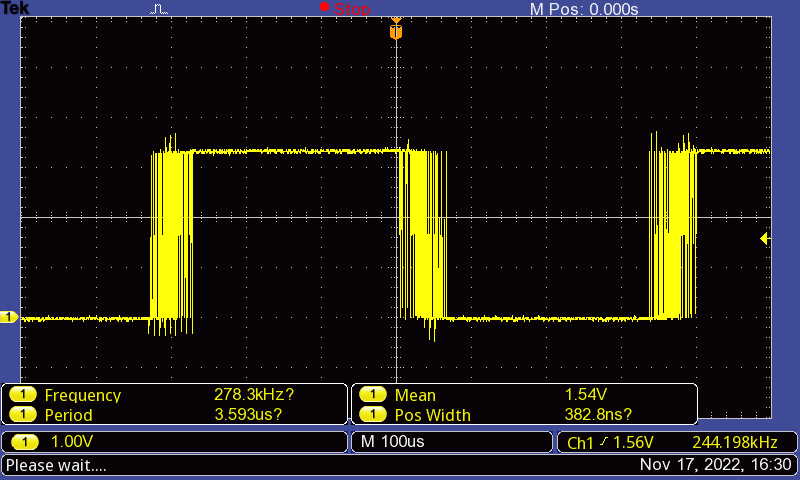
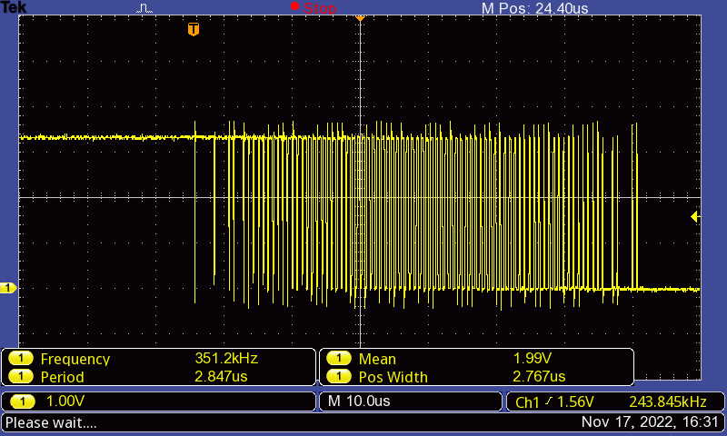 This isn’t a mixer difference frequency, it’s the result of jitter on (relatively) close frequencies. Here the input is 10.14018 MHz and the NCO is running at 10.1387 MHz, giving a 1.483 KHz difference frequency. But we can’t count that mess!
So I added a simple digital filter after the mixer. This is a simple 8-bit up/down counter that limits at 0 and 255. It’s essentially an integrator, counting up when the input is a “1″ and counting down when the input is “0″. The output goes high when the count hits 255, and stays high until the count hits 0. This results in a low-pass filter with a cutoff frequency of (100 MHz / 255) / 2, or 196 KHz. Here’s that same noisy mixer output after it passes through the filter:
This cleaned-up signal is then fed to one of the divider/timestamp stages and the timestamps are read by the uController, converted to frequency, and then sent over the counter serial port for logging or further processing. This serial port can only handle report rates of about 50 per second, so the divider has to be set appropriately. With a 1KHz mixer output the divider is set to 5 for a 50 Hz sample rate (or set to 100 for a 10 Hz rate.)
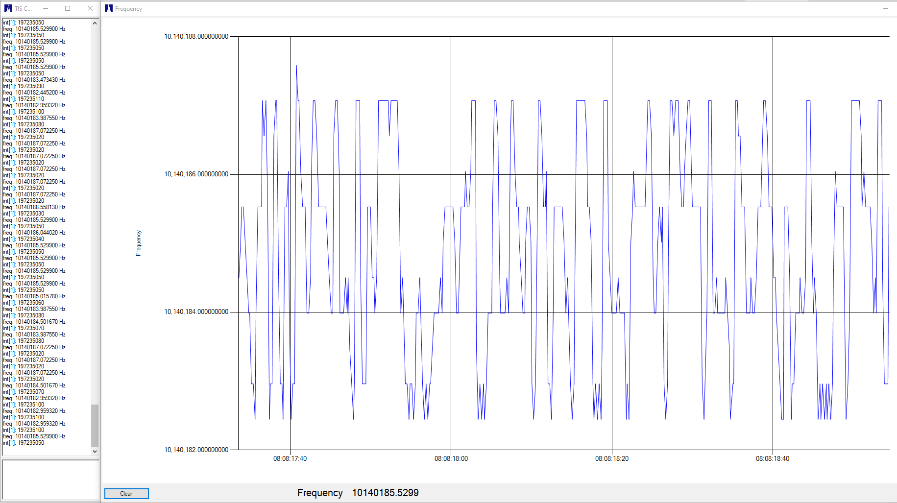
Here is a 10.140 MHz WSPR measurement, with the NCO set for a difference frequency of about 100 Hz. The divider is set to 5, giving a sample rate of about 20 Hz:
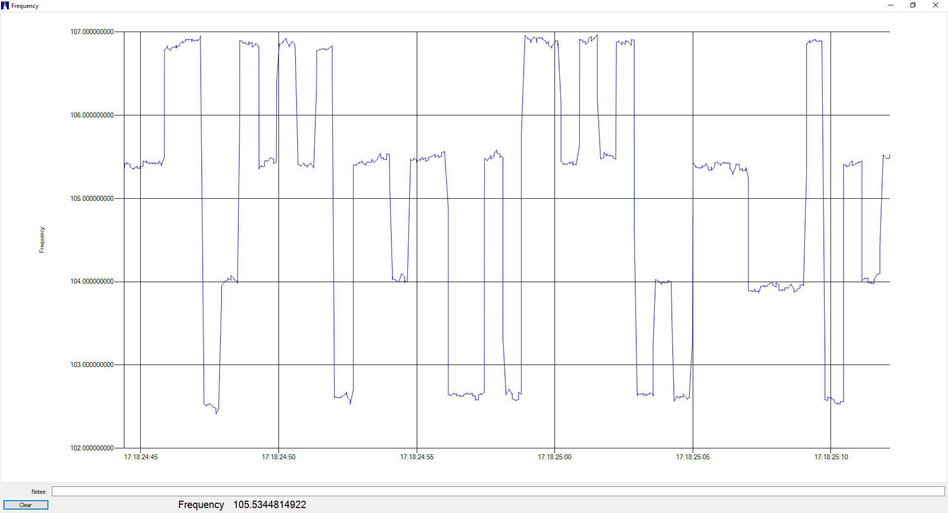 And here are some of the actual frequency measurements:
Note that only about seven digits are actually meaningful, but that’s still quite useful.
And unless I decide to do more processing with the local uController, because of the slow serial port update rate this mixer down-conversion method is only useful for fairly low-speed FSK measurements. Of course this is also useful when making other low-bandwidth measurements, such as clock drift.
And there’s still room left inside the FPGA! What’s next???
