Now that we know how to set the Si5351 to generate the FSK frequencies, we need to see about filtering (smoothing) the frequency transitions.
HF FM, using SSB:
- Audio FSK signal modulates SSB transmitter, creating upper-sideband signal. This is identical to FM
- Even with no explicit shaping, SSB transmitter audio filtering shapes the FM transient response
- WSPR and APRS have no filtering
- FT8/JS8 specify Gaussian filter, “BT = 2”, -3dB @ 12.5 Hz
With the Si5351 directly generating the transmit frequency there is no smoothing of the frequency shifts; the frequency change is a step function. While this can still be received and decoded, the frequency steps create significant in-band interference:
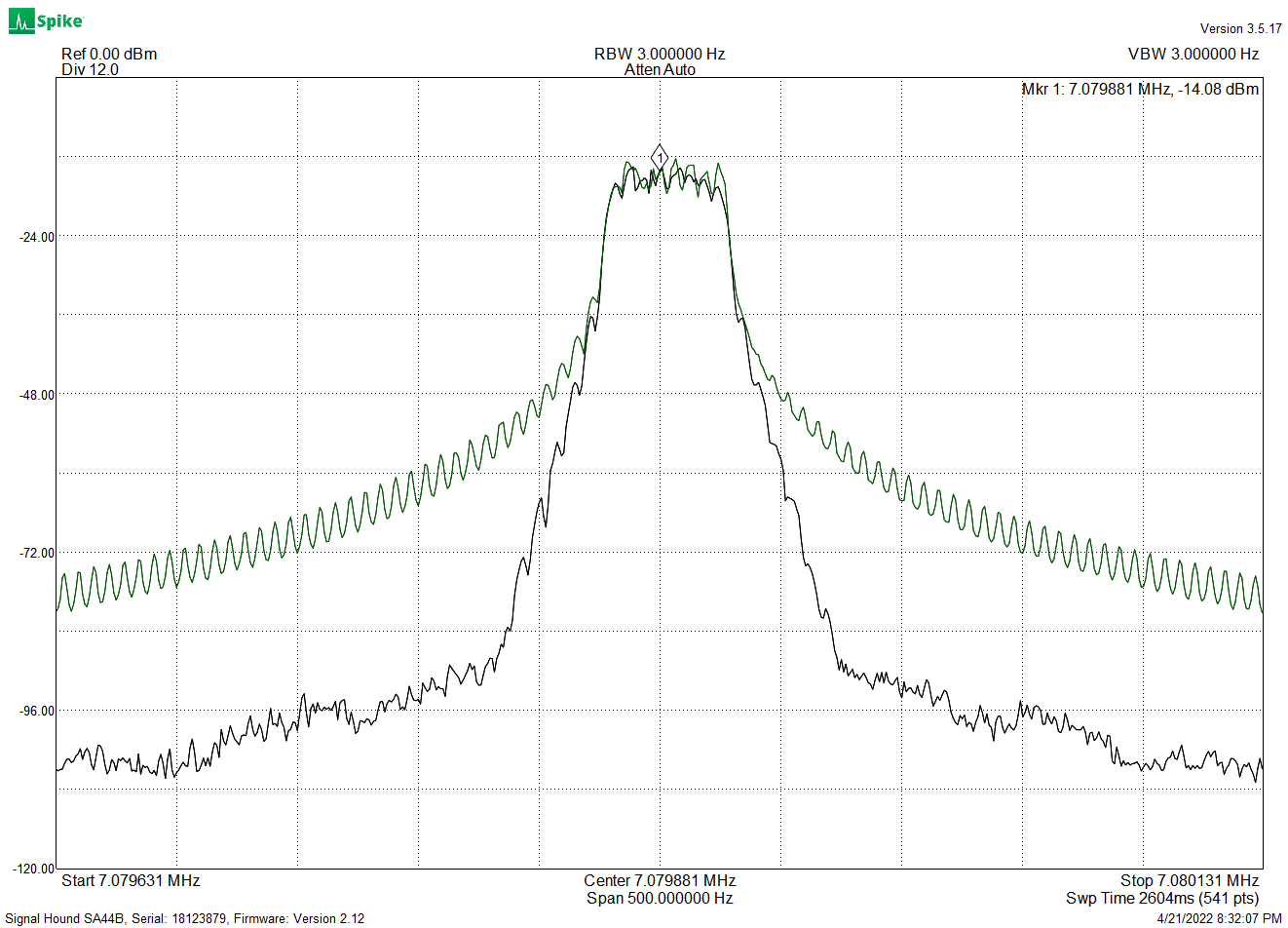 FT8 spectrum with and without filtering
In addition, in some cases the receiver uses a filter that is matched to the transmit filter, and having mismatched filters impairs effective signal detection.
The filter specified for FT8 is a Gaussian filter. This has a specific response, with characteristics that give good spectrum utilization. These filters have a fairly gentle shape, smoother than a simple RC filter:
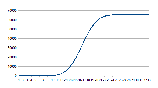 Gaussian Filter Step Response
Since we can’t use analog frequency-transition smoothing, we have to do this digitally, using small discrete frequency steps spread out over time. The Si5351 divisors give us the small frequency steps, and the Drift Buoy software uses a timer-tick interrupt running at a 2.4 KHz frequency to chop the given Baudrate into many small timesteps.
The Gaussian filter runs at this 2.4 KHz rate and using the large frequency steps as an input, generates a smoothed sequence of small frequency steps, which are used to update the Si5351 dividers. This filter is implemented in software as a Finite Impulse Response filter (FIR).
The “standard” FIR looks like this:
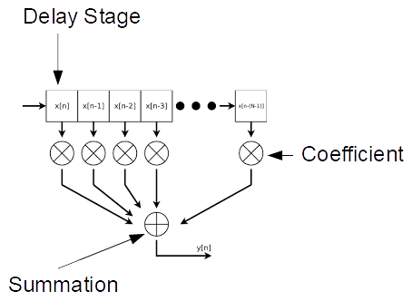
The input data is shifted through the delay-register chain, and at each shift the register contents are multiplied by the fixed coefficients and summed, giving the output. Many different filter responses can be obtained by selection of coefficients.
The Drift Buoy uses a simpler FIR structure, requiring no multiplications (there is one division operation for output scaling):
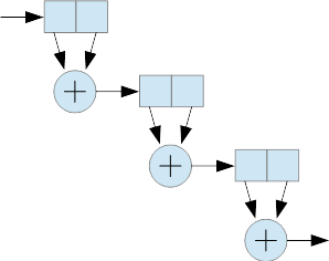
Each stage consists of two delay elements (these are 32-bit integer variables) and an addition. Stages are cascaded as shown, and the resulting filter response is Gaussian. The FT8 filter is clocked at 2.4 KHz and has 384 stages, which gives a -3dB response of 12.5 Hz. The filter function takes about 50us per sample.
In the case of FT8, there are 40 available frequency steps from one of the eight tones to the next. FT8 transmit data generates the eight tone values (0, 1, 2 … 7) . These are mapped to the values (0, 40, 80 … 280), which are sent to the filter.
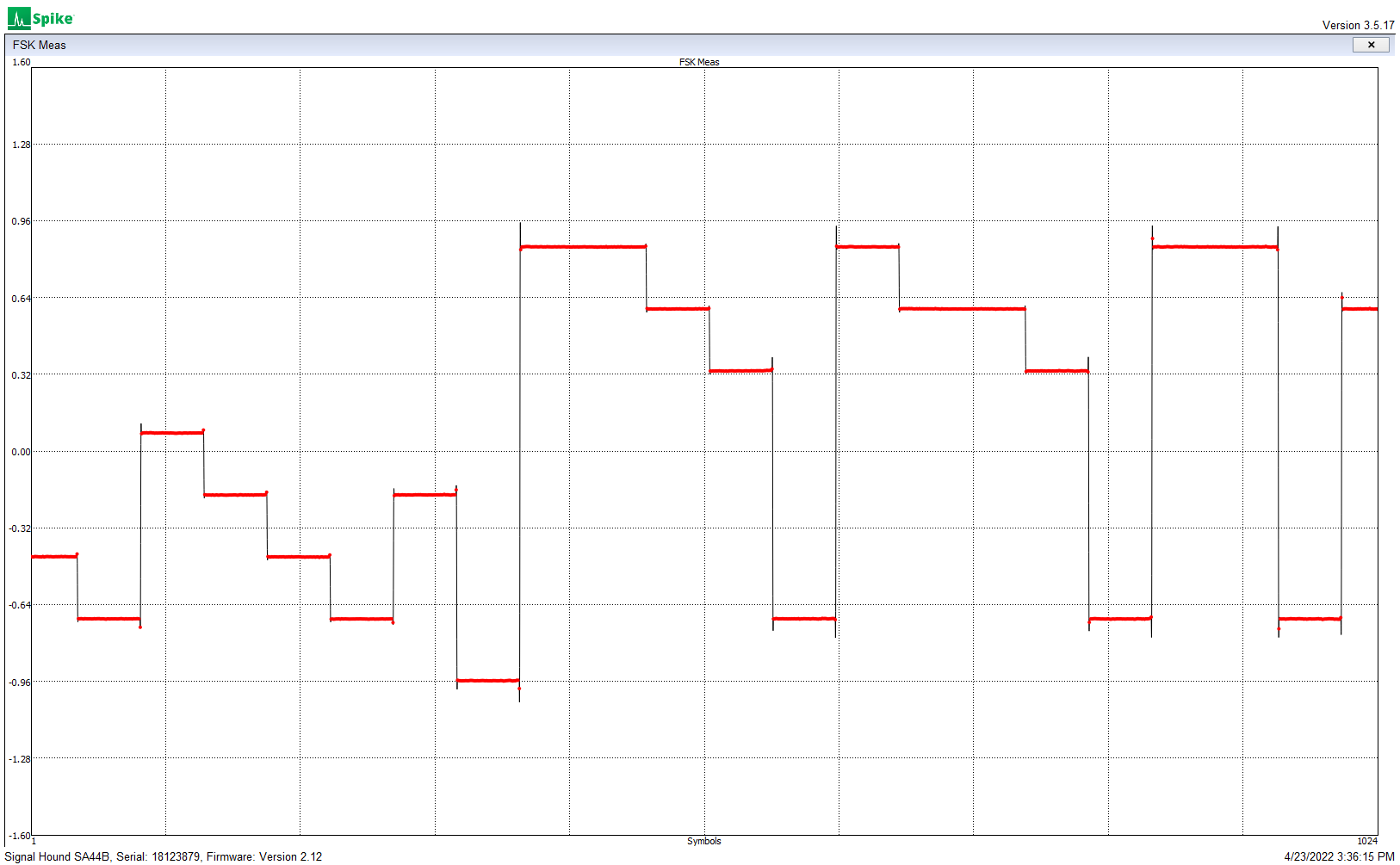
Unfiltered frequency steps
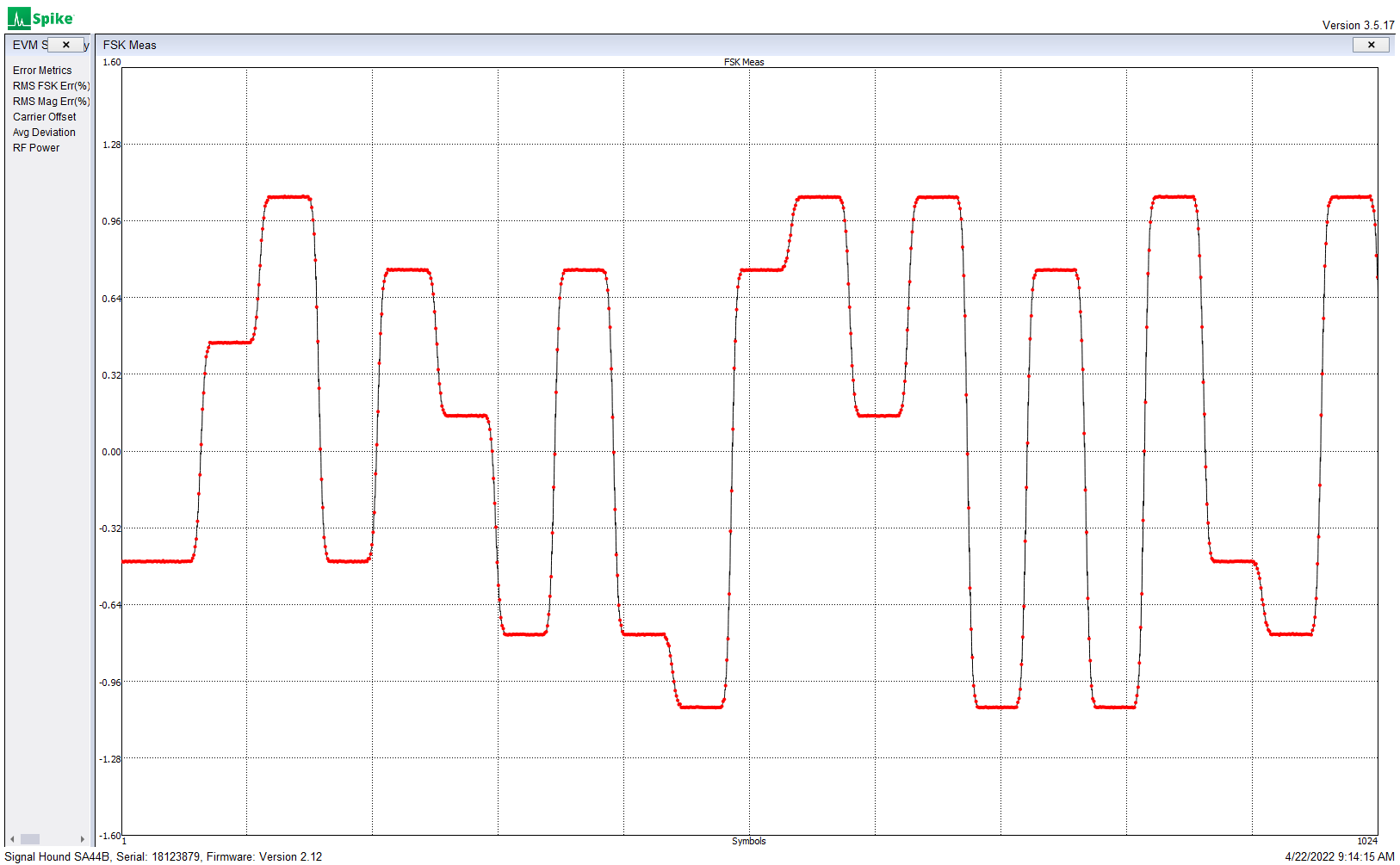
Gaussian filtered frequency steps
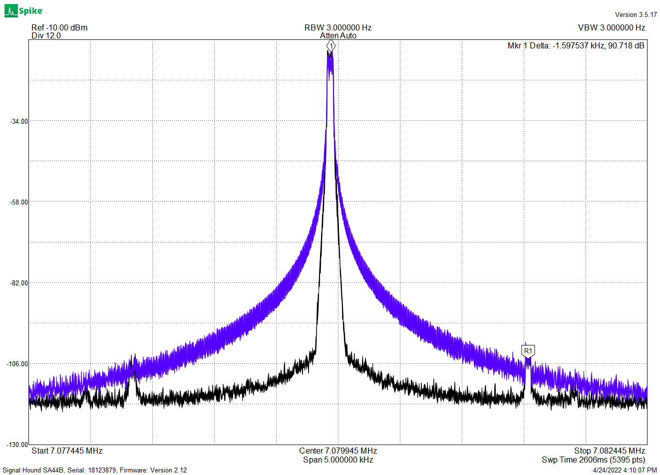
Unfiltered (blue) and filtered (black) 8-FSK spectrum,
showing 1,6 KHz sample-rate artifacts
The above plot shows the performance of an earlier version of the FIR, which was running at a 1.6 KHz sample rate. Increasing this rate to 2.4 KHz pushed the sampling artifact further out and reduced its amplitude. Updating the Si5351 at the 2.4 KHz rate required speeding up the I2C interface and optimization of the register updates — more on this to follow.
While WSPR and APRS have no filtering requirement, for these modes the Drift Buoy uses a four-stage Gaussian FIR, clocked at 2.4 KHz, to provide filtering similar to the audio bandwidth of a SSB transmitter.
Next: