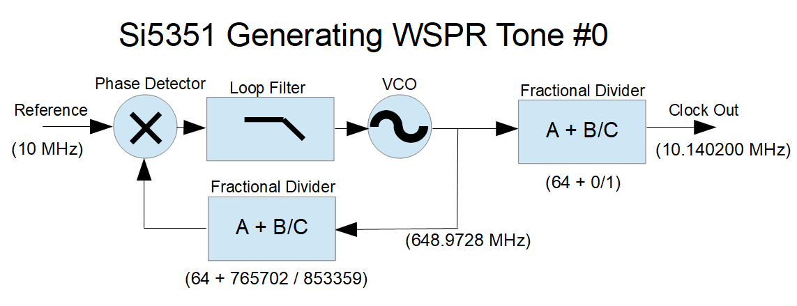
This is a simplified illustration of the Si5351, as configured to to generate the WSPR frequencies used in the Drift Buoy design.
The reference comes from a 10 MHz TCXO, which provides acceptable stability. The TCXO has an initial frequency accuracy of +/- 2.5ppm, which gives a +/- 25 Hz accuracy at the 10 MHz transmit frequency. Better initial frequency accuracy and secondary digital temperature compensation can be achieved in software, but this is not necessary for Drift Buoy operation
The output divider is programmed to divide the PLL VCO frequency by 64 (no fractional component), which provides the cleanest spectral output. The output divisor must be chosen so that the PLL frequency is within the available 600-900 MHz range. The FSK is done using the PLL feedback divider to vary the PLL frequency.
Determining the PLL divider values is fairly simple. We start by taking the desired output frequency (in this case 10.1402 MHz) and multiplying it by the output divider value (here, 64). This gives us a PLL frequency of 648.9728 MHz. We then take this PLL frequency and find the feedback divisor that will give us our reference frequency (here, a divisor of 64.89728 matches our 10 MHz reference).
So how do we set our “A + B/C” fractional divider to give us a ratio of 64.89728? The “A” value is easy, that’s just 64. We could set B = 897,728 and C = 1,000,000 — that would work, and setting C to one million makes the math easy. But WSPR FSK tone spacing of 1.4648 Hz requires precise frequency control, and with a denominator of 1,000,000, incrementing the numerator by one gives a frequency change of 0.15625 Hz and you can’t get a 1.4648 step with that increment. You can get close, probably close enough, but with a little math we can select divisor values that work much better.
Here’s a useful (very simple) equation for finding a PLL fractional-divider denominator when you are searching for a particular frequency step:
Fx = reference oscillator frequency in Hz,
OutDiv = output stage divisor. This can be an integer or a fractional division,
Fdelta= desired output frequency step in Hz.
PLLdenom = PLL fractional divider denominator (the “c” in a + b/c)
Here’s the relationship. Fdelta= Fx / (OutDiv * PLLdenom).
Rearranging this, we get: PLLdenom = Fx / (OutDiv * Fdelta).
So for WSPR, we have:
- Fdelta = 1.4648
- OutDiv = 64
- Fx = 10e6
Which results in PLLdenom = 106669.8525
Since the “C” denominator can only hold integer values, we could round up to 106670, but we can do better. The “C” value in the Si5351 fractional divider can be any value up to 1,048,575 (which is 2^20 – 1), so we can multiply this PLLdenom by 8, giving a rounded-up “C” of 853,359 (we could also multiply by 9 and still stay within the limits, but for some unknown reason I am using 8). With this numerator we have a minimum frequency step of 0.18309996 Hz. Incrementing the “B” numerator by 8 gives steps of 1.46479969 Hz — well within a microHz of the WSPR spec. We will use these small steps later, when we do Gaussian filtering of the FSK modulation.
So what about the “B” numerator? With B set to zero, the output frequency will be Fx * A / (output divider), or in this case 10MHz * 64 / 64, or 10 MHz. To get the desired 10.1402 MHz we need to set the “B” numerator to (10,140,200 - 10,000,000) / 0.183099961, which equals 765702 (rounded). Alternately, we can take the original 64.89728 divisor from our first calculation, and multiply the fractional part by C/1,000,000 which also equals 765702 (rounded).
There are ways to achieve even finer frequency resolution, by changing both the “B” and “C” values — see the “Farey Sequence” — but the simple method used here requires only one parameter change, allowing for faster configuration of the Si5351 (more on that later.)
This example was for WSPR modulation, but the principles apply to the other FSK modes.