After blowing up the transmitter power amplifier (1W) one too many times during test, I decided that it would be useful to put a current-limit circuit on my Charge/Boost board. This board takes the power from two 1W solar panels, and uses that to charge the Li-ion battery in a controlled manner. The battery powers the Drift Buoy and, through a switching boost converter provides 13V to the transmitter amplifier stage.
The Class-E transmitter amplifier is sensitive to loading, and a badly-matched load can cause excessive power dissipation or over-voltage in the transistors. In the process of trying to determine the safe limits for the amplifier I’ve managed to smoke a few transistors.
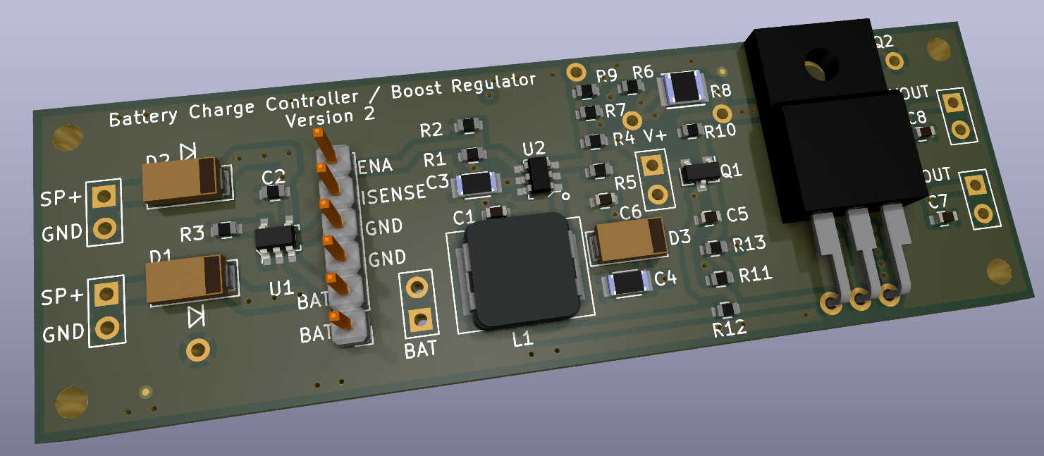
So the new regulator design now includes foldback current-limiting. I’ve added more test points and several configuration options to this board (not all parts will be stuffed at the same time), allowing for easy experimentation. The previous board had two layers, but this one uses four. The additional cost is minimal and this allows for a much nicer layout.
The current-limit won’t protect the Class E amplifier under all circumstances, because the amplifier efficiency is due to the careful phasing of transistor voltage and current. Different loads (resistive and reactive) will cause both amplitude and phase shifts of the voltage and current at the transistor so even with current-limiting there can be excessive transistor dissipation. Current limiting will help but I also have a big bag of transistors. And they’re cheap: about 17 cents each.
I should have test results in a couple of weeks.