As mentioned, I still needed to build the Li-Ion battery charger / boost regulator board.
This charger circuit takes the output from two 1W solar panels and uses that power to charge the Li-Ion battery. The charge-controller is not an MPPT design, just a linear regulator with other features. But the solar panel output voltage fairly well matches the Li-Ion requirements, so not enough power is wasted to justify using a more complicated circuit. The charger provides a signal output that indicates the charging current, and the Buoy controller monitors this and the battery voltage so we should have a good idea of the battery state.
The boost converter input comes from a Li-Ion battery, nominal voltage 3.7V to 4.2V. The output is 13.4V, nominal load about 100mA (this powers the Buoy 1W 10MHz power amplifier.
So, I collected the components, dabbed solder-paste on the PCB, hand-placed the parts, and put it in my converted toaster-oven reflow oven. It came out great, but I discovered that I had four resistors mis-identified on the silkscreen. I also was missing a couple of the resistor values so I had to to substitute some that were physically too big. The completed boards looks good, except where I had to hand-solder to correct my mistakes:
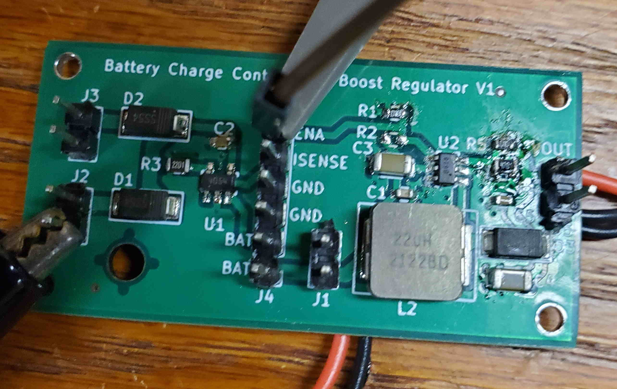 (I need to clean off that scorched flux!)
I hooked it up to some test gear and put the boost converter through its paces. I measured about 87% efficiency for the converter, and only a few degrees temperature rise for the components:
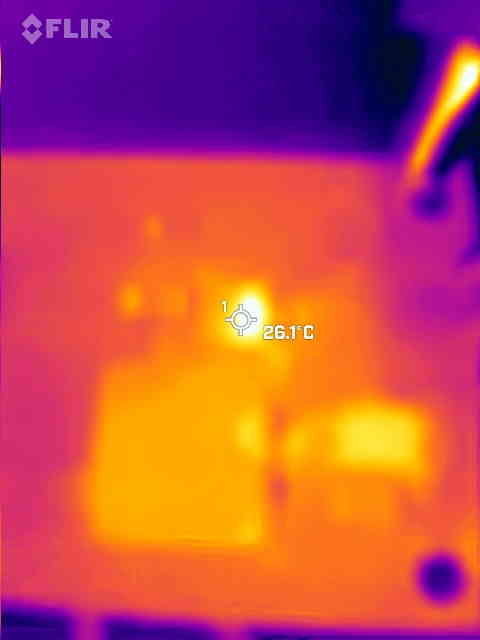 Thermal Scan
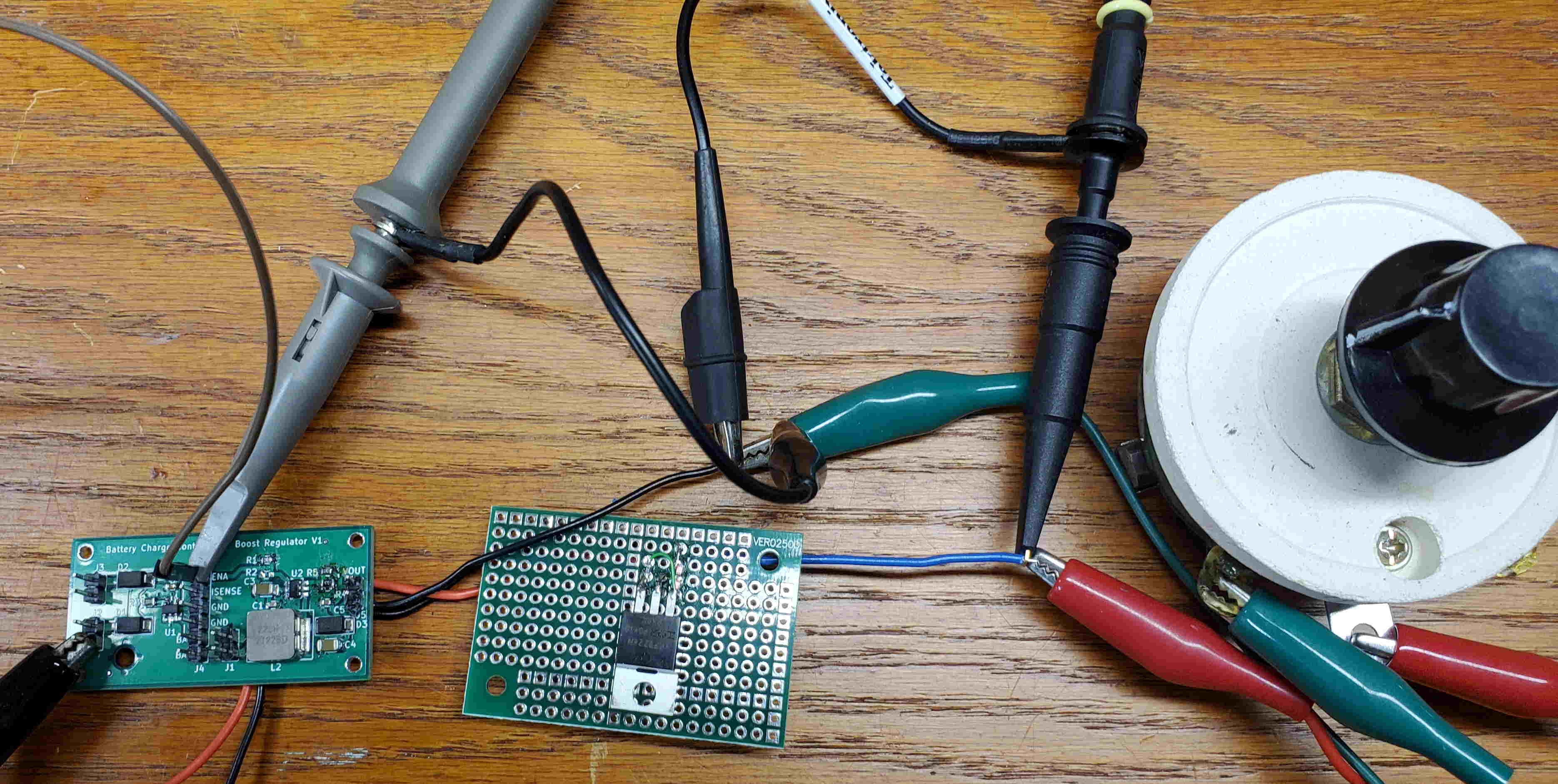 Testing the boards
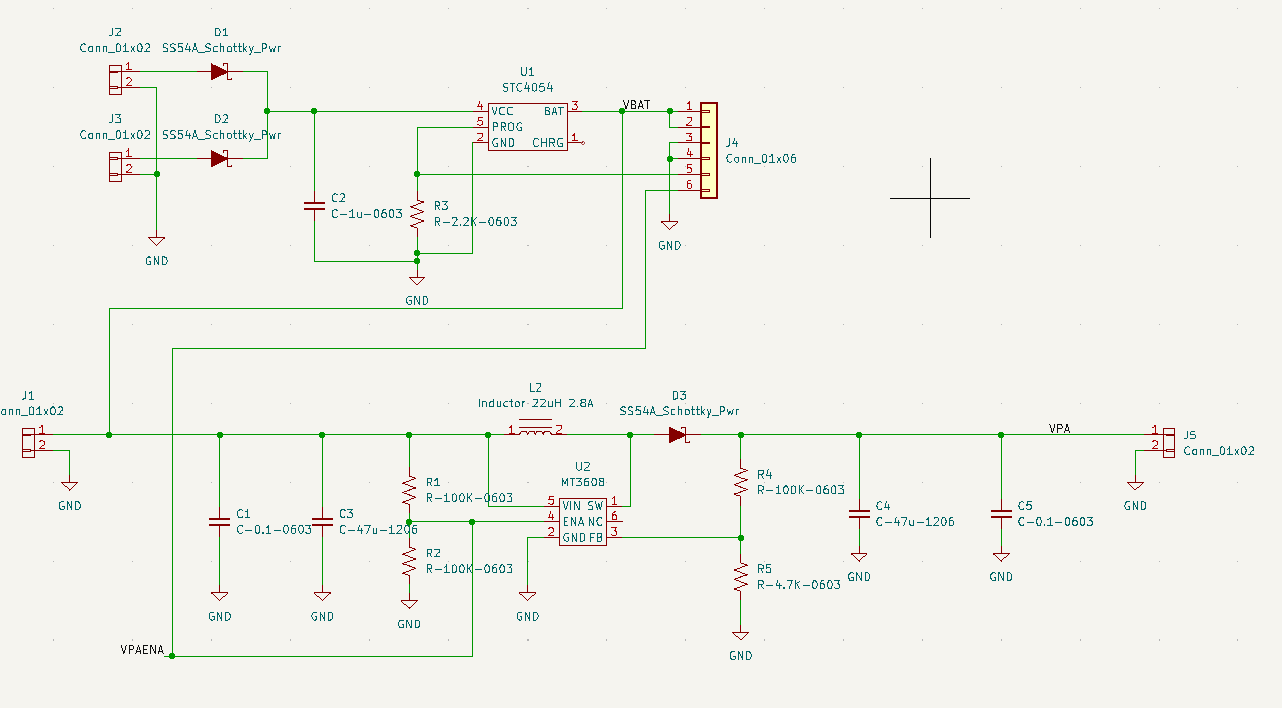
See that little perfboard with the transistor? That fixes a problem with my overall design. The boost-converter chip has an enable pin, and I am planning to use that to get software control of the amplifier power. Well, the converter shuts down, but even then the Li-Ion battery voltage still sneaks through the converter circuit (through the inductor and diode), applying about 3.5V to the amplifier:
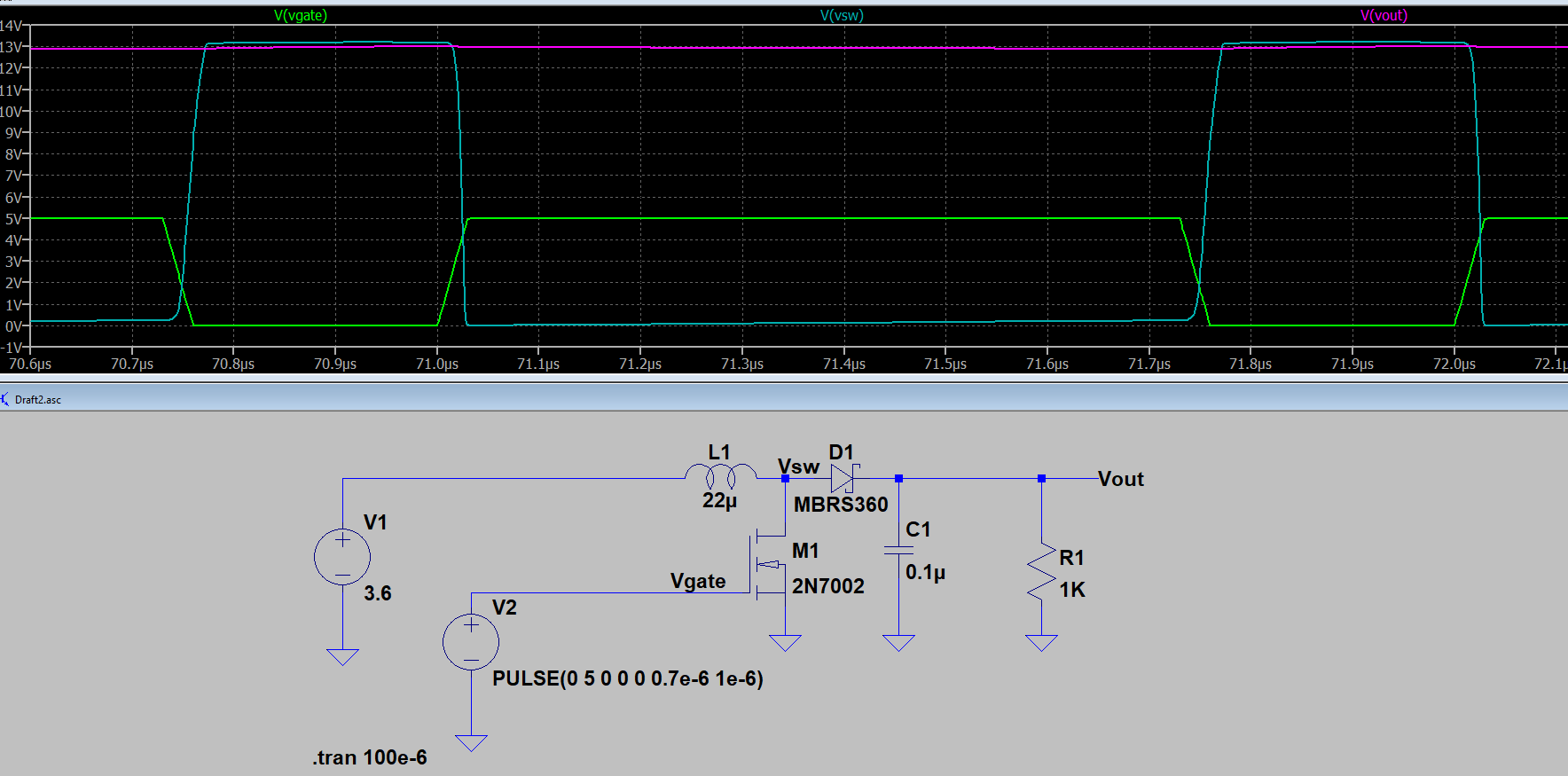 Essential Boost Converter Circuit
I ended up inserting a PMOS FET switch between the converter and the amplifier, which disconnects when the input is under 5V. It works quite well, and those two LEDS used as low-voltage Zeners, (sort of) gently glow when power is applied (about 0.1 mA through the LEDs):
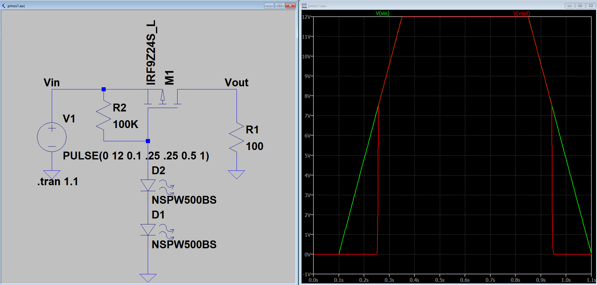 Low-Voltage Shutoff Circuit
I’m not done with this board yet, I still need to test the solar panel and charger circuit. I was worried about that boost converter ripple (it switches at about 1MHz) getting into the transmitter output. I’ve got LC filters on the power input, but is that enough?
Good news: testing shows no detected switching-related spurs above my -80dBc noise floor.