Since I am so enthusiastic about the fractional dividers used in the Si5351 (and about fractional dividers in general — in my career I’ve designed these into many telecommunications projects), I thought it appropriate to describe some details.
There are many types of dividers used in frequency synthesis and clock generation. The basic “divide by N” counter will take an input clock and output a clock at the frequency of (input / N). N can be any integer. This works well if you want to generate (say) a 2 MHz clock from a 10 MHz input — just divide by 5. But if you want to generate a 4 MHz clock, or a 1.875 MHz clock you just can’t get there from here using a plain divide-by-N.
Another divider commonly used in communications design is the Numerically Controlled Oscillator (NCO), which is essentially an adder and an accumulator (register bank).
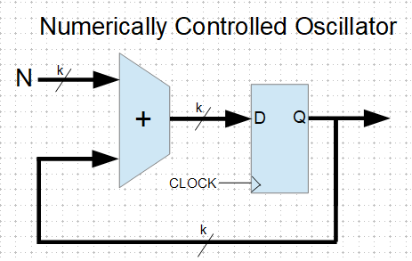
The adder takes the accumulator output and adds a constant value (the addend “N”), the sum going back into the accumulator. The accumulator overflows once per output cycle. If you wanted to generate that 1.875 MHz signal from your 10 MHz clock, you could use a 4-bit NCO, with the addend = 3. This gives you a division of 16/3, and an output frequency of 1.875 MHz. With this 4-bit NCO you can get ratios of 1/16, 2/16, 3/16 … 7/16, 8/16. Interestingly though, you can’t divide by 5, you can only divide by (2^k)/N, where k is the size of the accumulator. If you increase the size of the NCO you can get arbitrarily close to any desired fraction, and NCOs of 32-bits and larger are common.
The NCO also has the useful feature of providing a parallel output that can be used to drive a sine (or other function) lookup table, which can be used to generate low-distortion, low-jitter signals. Modern function-generators and radios usually use NCOs for this reason.
But sometimes you just need (or want) to divide precisely by some arbitrary number that isn’t limited to an integer or related to a power of two. Or, you don’t need the parallel output of the NCO. This is where the fractional divider (FD) comes in. There are ways to work around this NCO divisor limitation by dynamically altering the addend, but this complication may not be warranted. The FD has a shorter datapath and uses fewer gates than the NCO, which translates to higher speed, lower power, smaller chip area, and lower cost. It can fit and operate where NCOs just don’t.
The fractional divider is sometimes called a “clock-dropping” divider. For example, to divide by 2-1/2 (or 5/2), the FD will divide by 2,3,2,3,2,3… ![]()
To divide by 3-2/3 (or 11/3) the FD divides by 3,4,4,3,4,4…
Dividing by 8-1/2 (or 17/2) gives this output: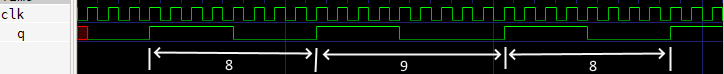
You can see that the output signal is “stretched” by one clock-cycle at a regular rate. This stretching, or dropped-clock, causes jitter, or frequency modulation of the output clock, which may need to be filtered out. In the “8-1/2″ example above, with a 10 MHz input the output is 10 MHz / (8-1/2), or 1.17647xxx MHz, and the repeating “8,9,8,9″ pattern at the output creates a frequency modulation of 1.17647xxx MHz / 2. The Si5351 uses a delay-line interpolator on the output FD which very effectively cleans up this jitter modulation. The jitter from the FD used in the Si5351 PLL is attenuated by the PLL loop filter. In other FD applications this filtering can often be performed by a simple bandpass filter.
For what it’s worth, sometimes with an NCO we want to use only the most-significant bit, and in this case there will also be this type of dropped-clock jitter. That’s just a fact of life with a purely synchronous design.
Extreme frequency resolution is a powerful feature of the fractional divider. For example, take the divide value of 8+25/100. This is of course equal to 8.25 . But change the fraction to 8+32/127 and we get 8.251968xxx. The fraction 8+31/123 equals 8.252032xxx. Since the Si5351 allows for numerator and denominator values up to 1,048,575 there is the potential for extreme precision. Look up the “Farey Sequence” for more information on the resolution of fractions.
There are many ways to implement a fractional divider. Here is a version designed in Verilog, which is a language used to design logic to be synthesized into an FPGA or other ASICs. This design uses an 8-bit counter, which can generate any ratio N/D, where (1 < D < 64) and (1 < N < (D / 2)).
module frac(
	input clk,
	input rst,
	input [7:0] b,
	input [7:0] c,
	output reg q
	);

	reg [7:0] sr;

	always @(posedge clk) begin
		if (rst) begin
			sr <= 8'b0;
			q <= 0;
			end
		else if (sr[7]) begin
			sr <= sr + b;
			q <= ~q;
			end
		else sr = sr - c;
		end
endmodule
I have based this design on the “Bresenham line-drawing algorithm”, which was originally a very clever way to draw sloping lines on a graphics display without needing to use floating-point math. This algorithm has proven useful in many other fields, including clock synthesis.
The fractional divider is flexible, simple, fast, and easy. So the next time you want to divide a clock by pi, just use a 355/113 fractional divider. That gets you to within 8·10−8 . Or if that’s not good enough, use 833719/265381 for better than eleven digits accuracy.