The small NUC computers such as the Beelink series are incredibly capable and have become the computer of choice for RX-888 SDR receiver installations that run ka9q-radio and wsprdaemon software. But providing these small computers with glitchless power can be a challenge. The small switching power supplies used with these computers do not store enough power to maintain their output voltage during brief power-outage events. Even the transient outages caused when a typical UPS switches into service have been seen to disrupt or reset the computer. The brief holdover provided by the TIS-1250 is sufficient to bridge the gap in power.
I’ve taken KA7OEI’s supercapacitor design and given it a few minor tweaks — it’s now available from Turn Island Systems.
Over at Turn Island Systems (TIS) and the HamSCI group, we are studying ways to measure Time Of Flight over various propagation paths and frequencies. We can currently do this crudely with WSPR and FST4W transmissions but the Time Of Transmit is only roughly known and the modulation characteristics only allow measurement accuracy in the millisecond region.
WWV and other frequency and time standard transmitters include precise timing information in their signals, but we need more transmitter locations and frequencies for a more complete data-set.
Work on the receive end is being done with the RX-888 SDR and ka9q-radio, and I have designed some units that provide a local in-band time reference signal for these receivers — testing is underway.
For the transmitter, some work has been done using GPS-synchronized 1-second BPSK. I am expanding this here to use not only the 1-second modulation, but also a faster PRBS data pattern that still complies with the new occupied bandwidth regulations. This is definitely a work in progress, and my transmitter will be turned on and off while we figure out the details. But for now, here is the signal format:
Carrier freq: 7.090 MHz
Minute 0: transmit morse ID message
Minute 1-2: transmit PPS BPSK
Minute 3-4: transmit PRBS DBPSK
Repeat
The PRBS pattern is the 1023-bit GPS CA code #1, 170.5 Hz chip rate, 10-second sequence rate. The modulation is DBPSK (NRZI/BPSK).
The transmitter location is Occidental, California, and the antenna is an off-center-feed 40 meter dipole. The photo shows my stack of little boxes I am using to generate these signals. From top to bottom they are:
TIS-1W One-Watt amplifier – logic-level in, square wave out, 1-50 MHz, powered via 5V USB-C. The input is provided by:
BeaconBox – a lightly-modified early TIS test board, designed during the early stages of the TIS WSPRSONDE. This is connected to a GPS antenna for time and frequency synchronization. I am also giving this board a reference clock from an external 10 MHz OCXO.
A TIS Filter-Combiner – this takes the output from the 1W amplifier, turns it into a clean low-harmonics sinewave, and sends it to the antenna.
Note that the PRBS modulation is technically *not* Spread Spectrum (that may come later, pending rules changes). We have chosen this particular PRBS pattern because it is well-documented, and has good characteristics permitting potential multiple transmit sources to share a common frequency.
Acronyms, etc.:
PPS : Pulse Per Second
BPSK: Binary Phase Shift Keying
DBPSK: Differential BPSK
PRBS: Pseudo-Random Bit Sequence
GPS CA Code: Here’s a good link that describes this:
https://natronics.github.io/blag/2014/gps-prn/
Please contact me if you have any questions or comments!
paul (at) wb6cxc.com
I’ve got RF signal generators, and arbitrary waveform generators, but sometimes neither of these gives me what I need when testing mixed digital / RF circuits. For example, here is a board I designed to perform unfiltered BPSK modulation of an RF carrier. The purpose of this design is twofold; primarily to provide an in-band a timing reference signal for an SDR (or other receiver) when we are trying to measure the time-of-flight of radio signals such as WWV time-ticks. The other goal for this design is to allow me to experiment with slow-speed spread-spectrum-types of transmissions (yes, I am fully aware of the ham regulations and occupied bandwidth limitations.)
BPSK Modulator
For the time-sync generation we will inject into the receiver input a low-level carrier with a 1 Hz phase inversion, driven by the PPS output of a GPS receiver. The BPSK board takes a carrier input and the PPS input, and generates the BPSK output. The carrier will be at 84.225 MHz, which will be partially attenuated by the input filter of the RX-888 SDR. This frequency is above the Nyquist limit and so will be aliased down to 45.375 MHz by the RX-888 129.6 MHz sample clock. This specific carrier frequency was chosen so none of the aliasing artifacts of the carrier or the first five harmonics will land in any of “ham-interesting” bands, and so that re-radiation of it will be blocked by the external low-pass filter typically installed between the antenna and the receiver.
Yes, but what about the testing?
The carrier input port is designed to take a square-wave signal from a 50 Ohm source, with an amplitude of about 1.5 volts P-P (as you would get from a programmable-output GPSDO). But I want to use my spectrum analyzer tracking generator so I can easily see the frequency response of the boards output filter, and the analyzer can’t deliver an output (sine or square) at that level.
So I need to boost a small sinewave up to a logic-level square-wave. Fortunately I have the TIS-126 Clock Distribution Buffer handy:
TIS-126 Clock Distribution Buffer
TIS-126 Circuit Board
The TIS-126 buffer will accept a 1 Hz to 100+ MHz signal (sine or square) between -20 and +20 dBm, and deliver a 3.3V (unloaded) or 1.6V (50 Ohm load) square-wave output to six ports. In this case I only need one output port, but usually the TIS-126 is used to provide reference clocks to test equipment, or to multiple transmitters or receivers.
I connect the tracking generator output to the TIS-126 input, and drive my Device Under Test from the TIS-126 output, and can now view the filter response on the analyzer:
Test Results:
BPSK Modulator Output Filter / Attenuator Frequency Response
Here we can see the 84 MHz filter after attenuation. To be honest, I’m not sure about the response much above 100 MHz since the TIS-126 output will be falling off and quitting at some point — I didn’t check. But the filter response looks quite good.
And above is the spectrum of the unmodulated 84 MHz carrier and some harmonics that made it through (or around) the filter. For the intended application, the RX-888 input anti-aliasing filter, while marginal, should still attenuate these much further. Even if these harmonics break through the noise floor, the careful choice of carrier frequency makes sure that they will not interfere with our signals of interest.
And below is the spectrum of the 84 MHz carrier with a phase inversion at a 100 Hz rate:
BPSK 1/0 pattern 100 bits / second
Finally, the spectrum of an unfiltered 40 MHz carrier being BPSK NRZI modulated by a 250 bits per second quasi-random data pattern:
PRBS NRZI BPSK 250 bits/second
For some of these measurements, being away from my big RF generator, I used the Turn Island Systems TIS-5351 TinyClock for the carrier input. This little unit delivers a 1.6V P-P squarewave from about 10 KHz up to over 100 MHz. It’s petty handy, and can be connected to a reference clock when frequency accuracy is needed:
TIS-5351 TinyClock
Conclusion:
The main take-away is that with the proper amplification or buffering, your RF test equipment can be used when testing digital designs. There are many ways to accomplish this, I have the TIS units (and I designed these because I wanted to solve this exact type of problem), but it’s a pretty simple project to build your own. Details and some schematics are available on the TIS website:
As we push the envelope of SDR bandwidth with receivers like the RX-888, In addition to sample rate and aliasing concerns we also also need to look at the dynamic range issues. With traditional “analog” receivers the dynamic range is usually dominated by the IMD (intermodulation distortion) of the front-end preamp and the following mixer stage. Techniques to optimize dynamic range include pre-filtering and AGC (automatic gain control), which can be quite effective when used in relatively narrow-band operation.
But AGC and filtering aren’t so easy in a SDR that is receiving the entire spectrum from (say) 10 KHz to 60 MHz. There is a huge range of signal levels, especially when you are close to a megawatt-level broadcast transmitter. While the 16-bit ADC (analog to digital converter) in the RX-888, with it’s 96dB range, is clearly superior to the 12 and 8-bit ADCs used in many other SDRs, the real-world range of RF signals can easily exceed this.
By the way, the effective dynamic range of an ADC is often several dB better than is suggested by the number of bits, due to what is essentially noise dithering and oversampling.
In some cases the programmable attenuation provided by the SDR can be adjusted dynamically for the best use of the available dynamic range. In addition, there is always the possibility of digital overload and/or digital gain control via numerical scaling within the numerous digital signal processing stages of the software. These are subjects for a different discussion. Here, I’m talking about filters.
While some amount of ADC over-range clipping is tolerable, we usually try to minimize this by inserting attenuation or otherwise setting the gain before the ADC sufficient to avoid significant overloads. We also use a moderate amount of frequency-shaped filtering to reduce input levels at lower frequencies where the general atmospheric noise establishes a higher noise floor. The Turn Island Systems SDR Filter and Filter-Preamp are examples of this type of filtering:
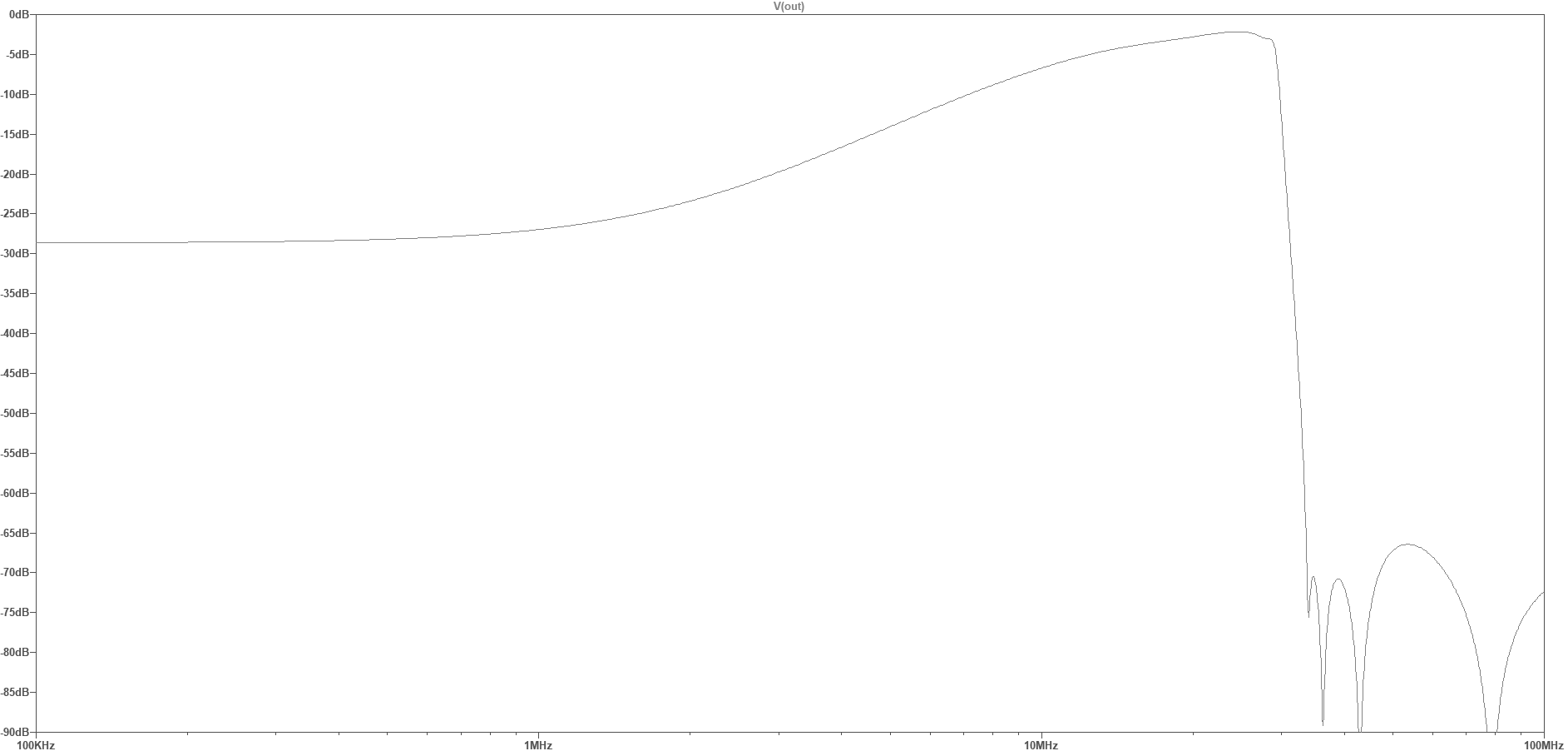
Shelf filter with 30 MHz anti-alias LPF
This filter has a steep 30 MHz anti-aliasing low-pass filter, and a high-pass “shelf” filter that attenuates the frequencies below around 10 MHz, flattening out below 1 MHz to a “shelf” attenuation of about 28 dB. This shelf filter roughly compensates for the change in the general atmospheric noise level, and attenuates the USA AM BCB (broadcast band, 540 – 1700 KHz) , helping reduce the chance of ADC overload.
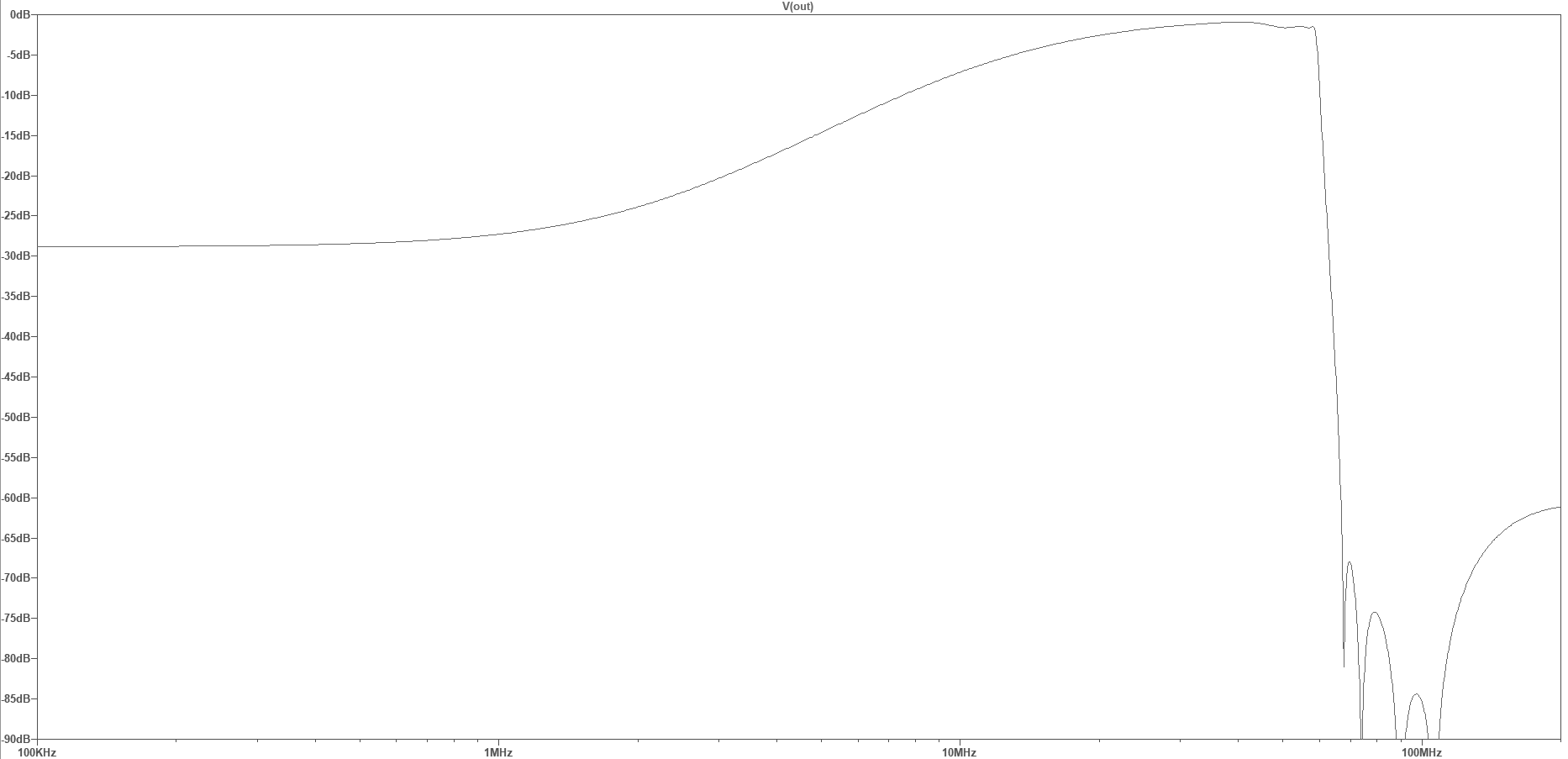
A similar filter/preamp (under development) places the LPF corner frequency at 60 MHz, allowing reception of the 6-meter ham band (requiring a RX-888 SDR sample rate of 130 MHz). This filter also has the stopband notches placed to optimize attenuation of the 88 – 108 MHz FM broadcast band, which would otherwise be aliased down to 22 – 42 MHz in frequency. While the RX-888 does have a built-in 60 MHz LPF, it’s characteristics are pretty marginal (see the links at the end of this post for more details).
Shelf filter with 60 MHz anti-alias LPF
While the shelf filter reduces the chance of AM BCB overload, strong signals elsewhere can still cause problems. If these are in the ham bands then simple filtering is not going to help. But some people are using tunable notch-filters to attenuate specific signals, or ham-band bandpass filters to attenuate out-of-band signals. Here is an eight-band bandpass filter I am currently working on (I’m calling it the BPF8):
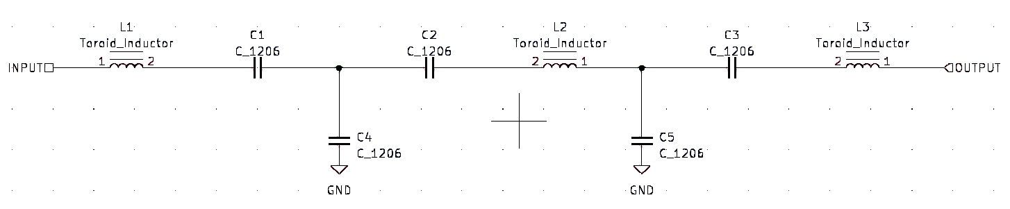
The BPF8 is actually a bank of three-section bandpass filters connected in parallel. Each filter has this design:
One of the eight band-pass filters
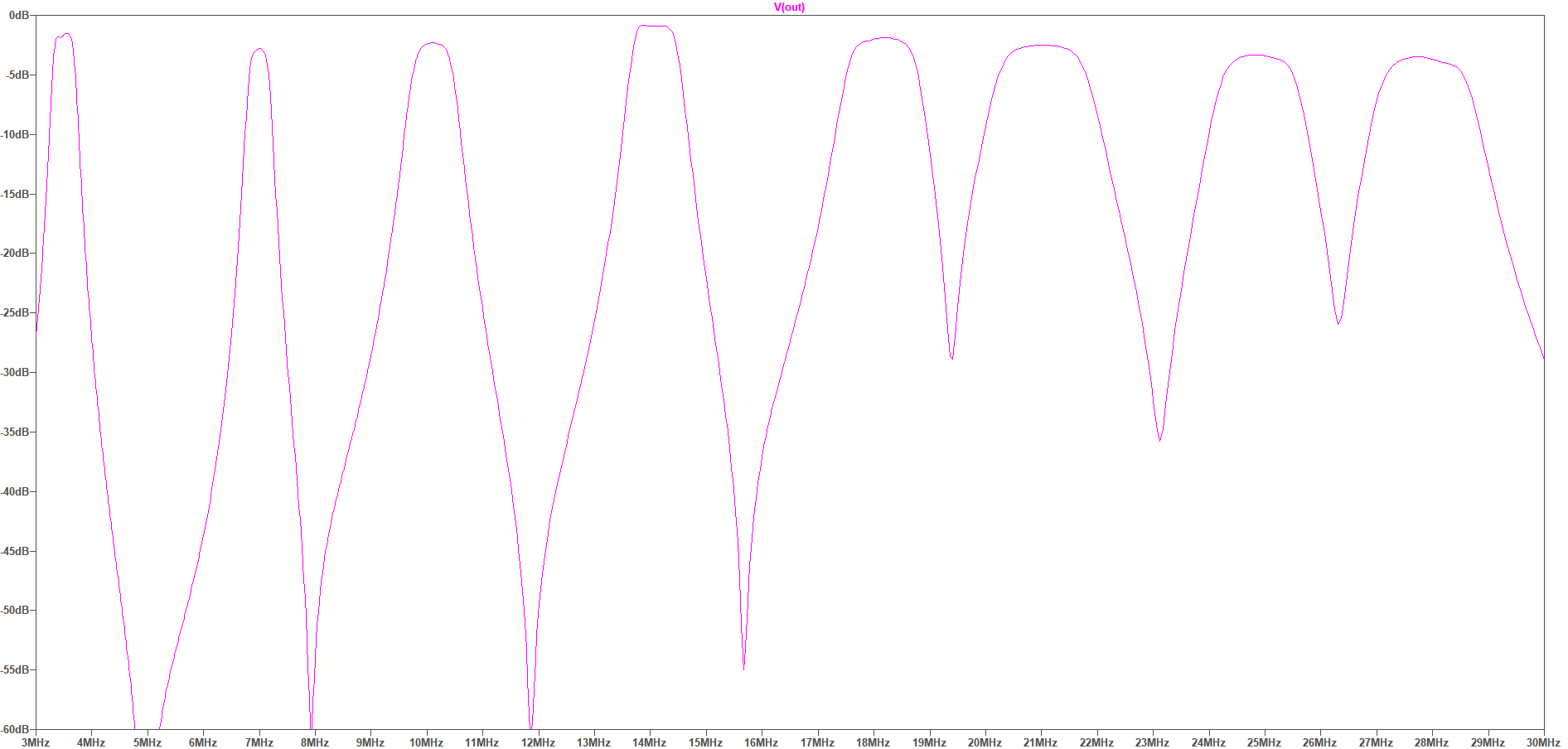
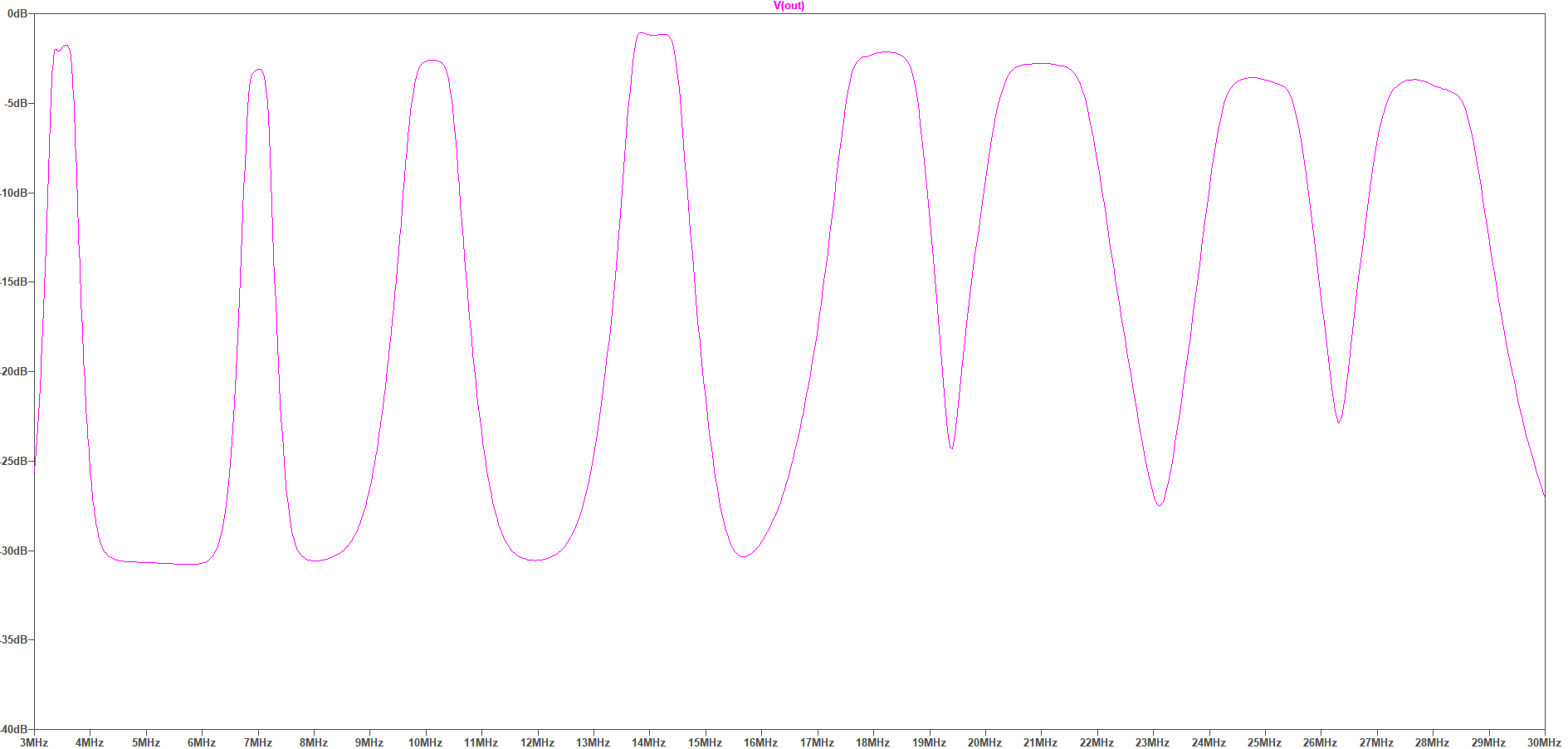
The (simulated) overall response looks like this, covering the 80, 40, 30, 20, 18, 15, 12, and 10 meter ham bands. These filters are tuned for the WSPR sub-bands:
BPF8 frequency response (linear frequency plot)
Will this help with SDR dynamic range? That depends on the interference — if the out of band signals aren’t strong enough to create problems then this filter will be unnecessary.
If reception between the filter bands is still desired, a broadband shelf response can be selected (via a jumper), which limits the maximum attenuation — here, to 30 dB:
BPF8 frequency response, -30dB shelf (linear frequency plot)
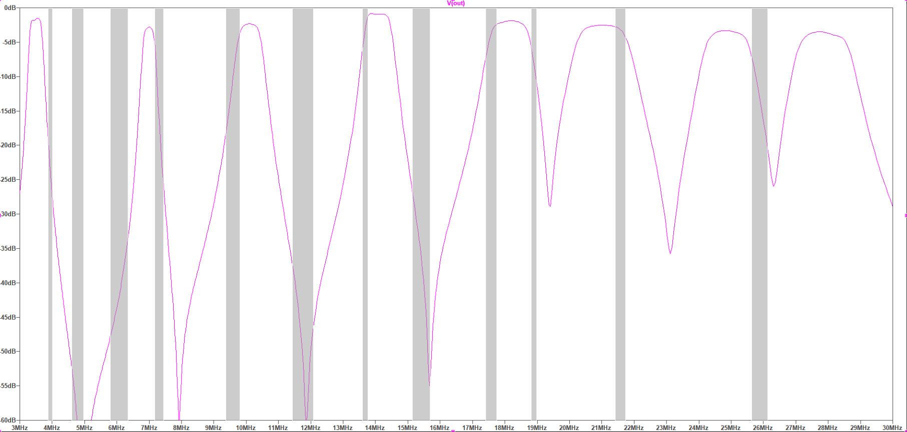
In the USA, most of the BCB signals are below that 1700 KHz frequency. But in Europe there are many powerful broadcast transmitters scattered over the HF frequencies, and these can cause big dynamic range problems. Here are the shortwave BCB frequency bands superimposed on the above multiband filter response (some of these bands are only lightly or regionally in use):
Shortwave broadcast bands
As you can see, some of these SW BCB frequencies are extremely close to the ham bands, and so in those cases the filter will probably not help much, while other SW BCB signals will be significantly attenuated. The BPF8 will probably include jumper options to optionally disable a selected filter section. Is the BPF8 worth a try? We shall see.
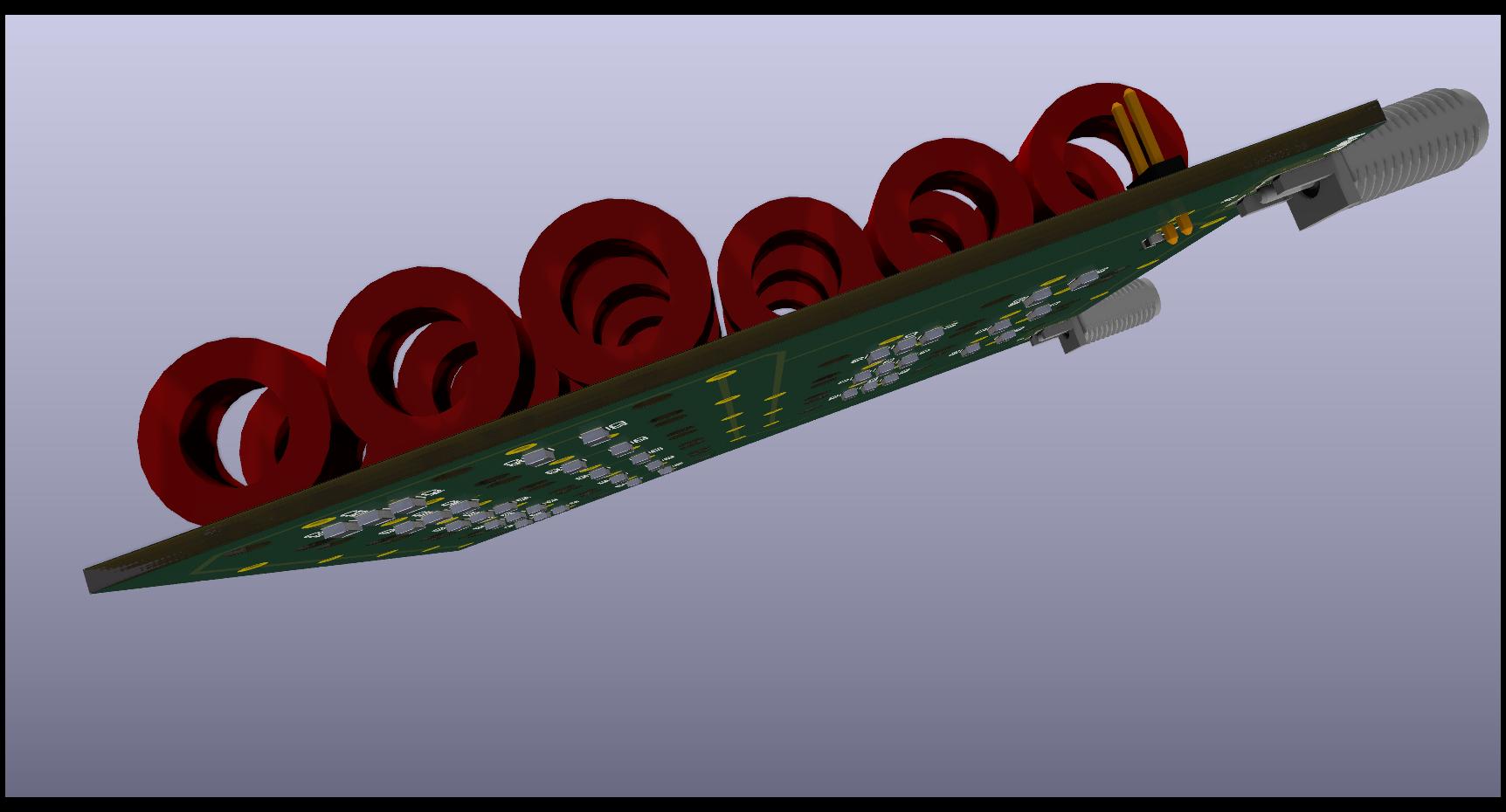
BPF8 circuit board
The BPF8 prototype board is densely populated with 24 toroid core inductors, used for their low-loss and self-shielding characteristics. The filter capacitors are on the underside of the board. This will be another “hard to build” design, because of all the hand-wound and tuned toroids, but I hope the results will be worth it.
For more details of the RX-888, and about shelf filters, look at KA7OEI’s blog for some excellent in-depth discussion of these issues: