I finally put the components on the SWR bridge board:
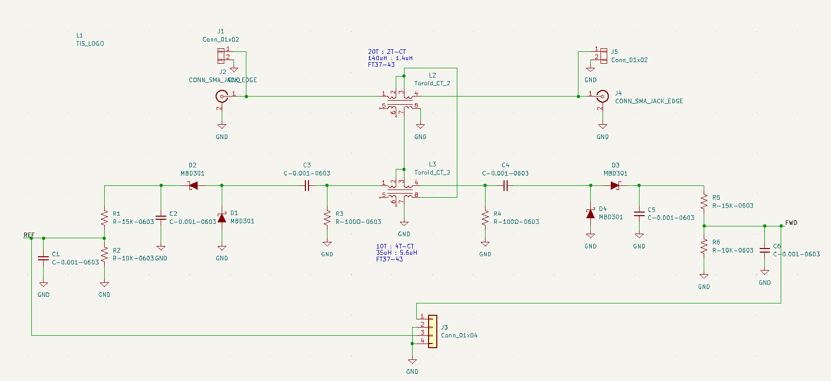 SWR Bridge Schematic
The SWR bridge uses a common two-transformer directional coupler design, and should have very low excess loss. Typically the coupled taps are designed for a 50 Ohm impedance, which makes perfect sense if you want to connect it to other test equipment. But here we are using a full-wave rectifier diode detector design, and we can reduce the loss, or increase the sensitivity, by scaling up the impedance at the coupled ports. Here I adjusted the transformer turns ratios to drive a 100 Ohm load at the detector ports.
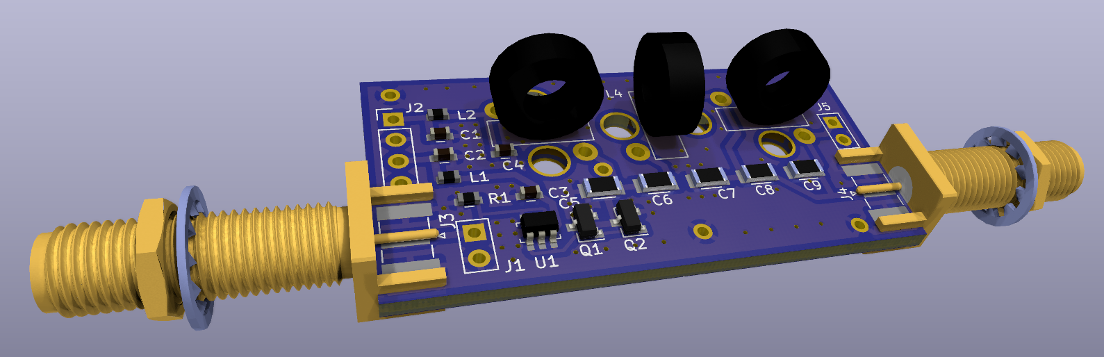
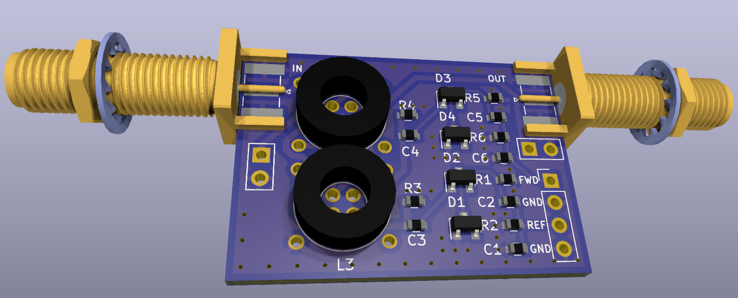 3D KiCad Rendering
It turns out that there is a downside to how quick/easy/cheap the design-to-PCB process is. First, I spent some hours simulating various circuit options in LTSpice Then, using KiCad for schematic capture and circuit-board layout, I had the schematic and PCB design finished in one evening. This included building some custom symbols and footprints for my toroid coils and the Schottky diodes I had chosen. That same evening I sent the PCB files over the internet to JLCPCB, and selecting the next-to-cheapest delivery option I had five boards fabricated and shipped for $12.80. Complete(!) These were two-layer boards, but four-layer are only very slightly more expensive. Since the component count was low, I chose to not get the stainless solder-paste stencil, but those are also quite inexpensive and certainly worth it if you have a more complicated board.
So what’s the downside? It’s so easy, quick, and cheap that I perhaps don’t spend enough time checking my work. Turns out I had four silk screened reference designators swapped (which meant I installed those parts in the wrong location), and I had screwed up the location of two diodes in my original schematic. Fortunately, all the traces are on the top side, and it was easy to cut traces and solder wires to fix that little SNAFU.
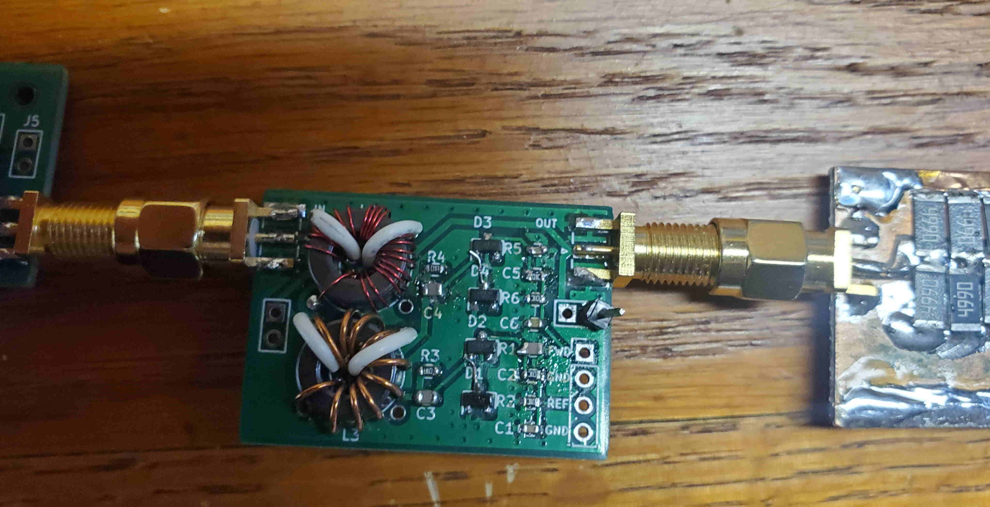 Board Under Test (with cuts and bodge-wires)
With those fixes I was able to test the SWR detector with my signal generator at +20 dBm (1/10 W), and using my Drift Buoy amplifier at +30 dBm (1 W). I was able to test with SWR of 1:1, infinity, 1.27:1, and 1.168 (these last two using a 10dB attenuator with open and shorted outputs). I’m going to have to do more measurements at different SWRs. I will be measuring the forward and reverse detector output voltages with the Drift Buoy A/D converter, and since the diodes are non-linear, will need to characterize the behavior at different power levels and SWR values.
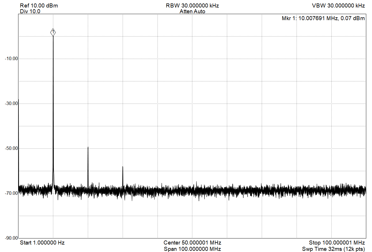
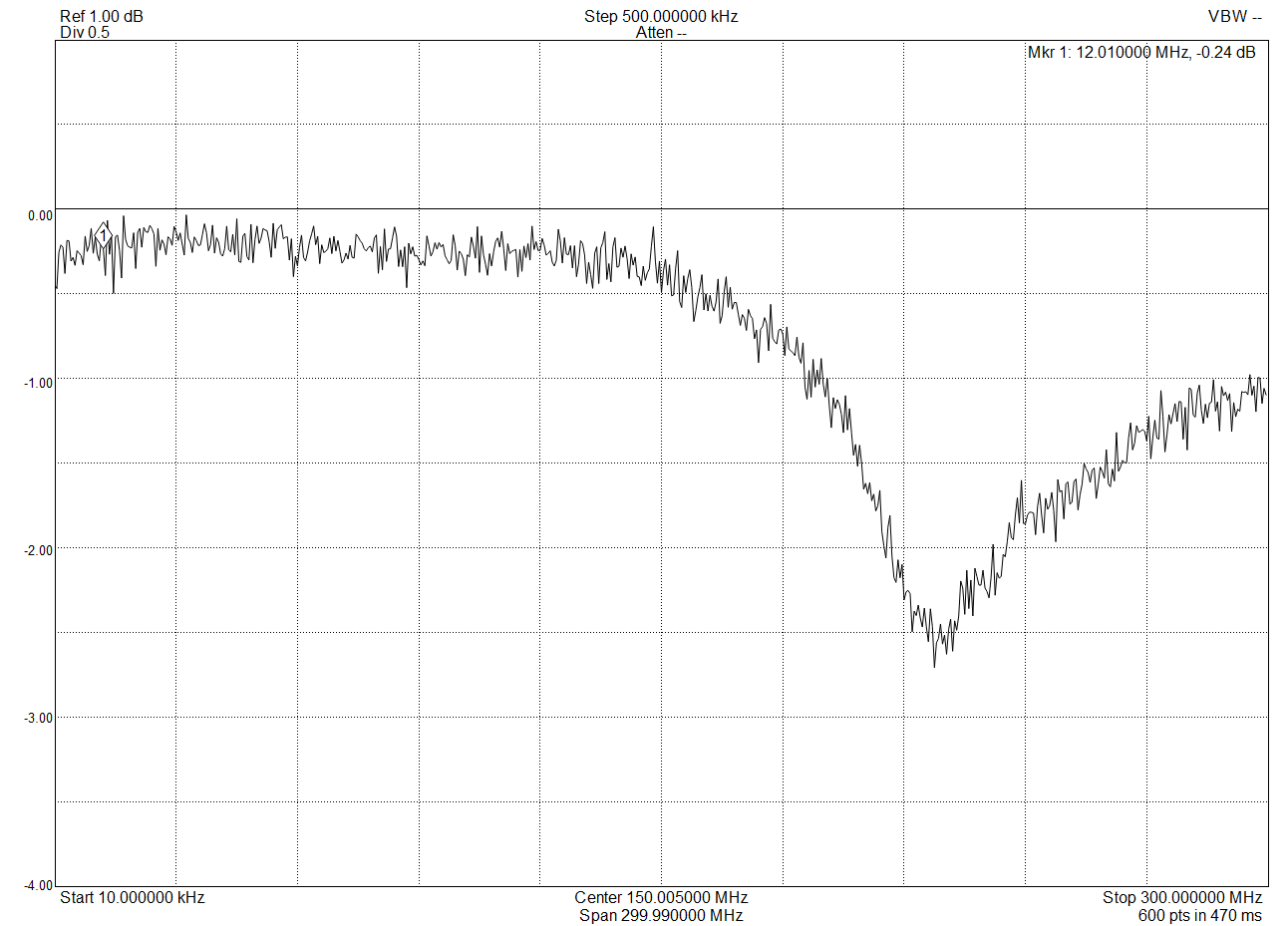 Through-Loss (-0.2dB @ 10 MHz)
The last test was a loss measurement using my spectrum analyzer and tracking generator. I hadn’t been too concerned about behavior far away from the 10 MHz frequency of operation, but it looks like the SWR bridge behaves well beyond 100 MHz. The loss at 10 MHz is about 0.2 dB, which is pretty good.
By the way, those white wires on the toroids are the two-turn center-tapped windings. I used a trace on the PBC for the center-tap connection and use two hairpin wires for the turns.
 (I need to clean off that scorched flux!)
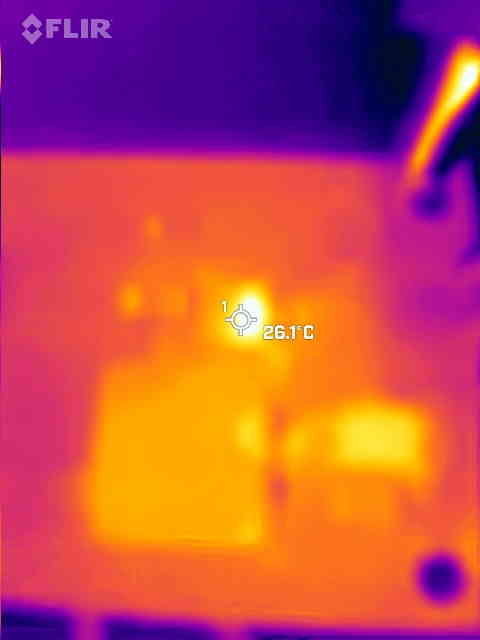 Thermal Scan
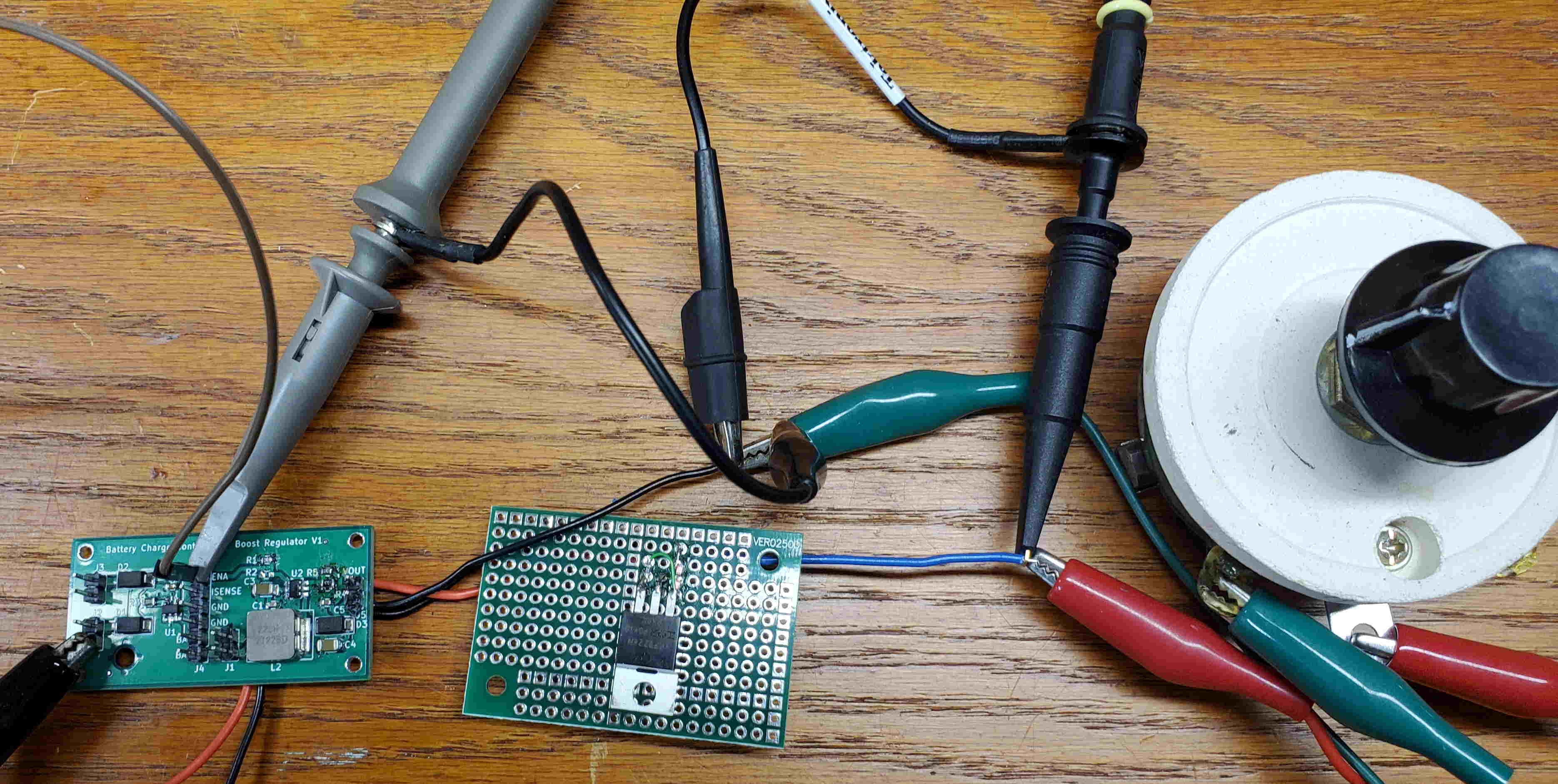
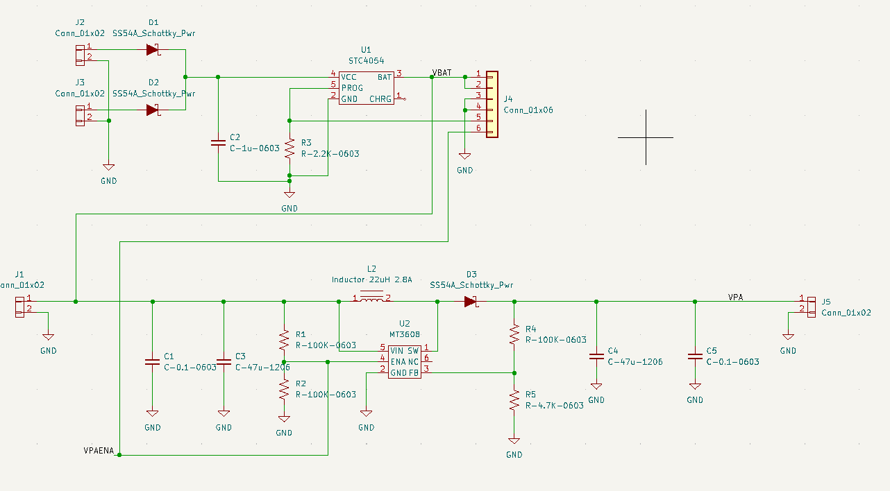
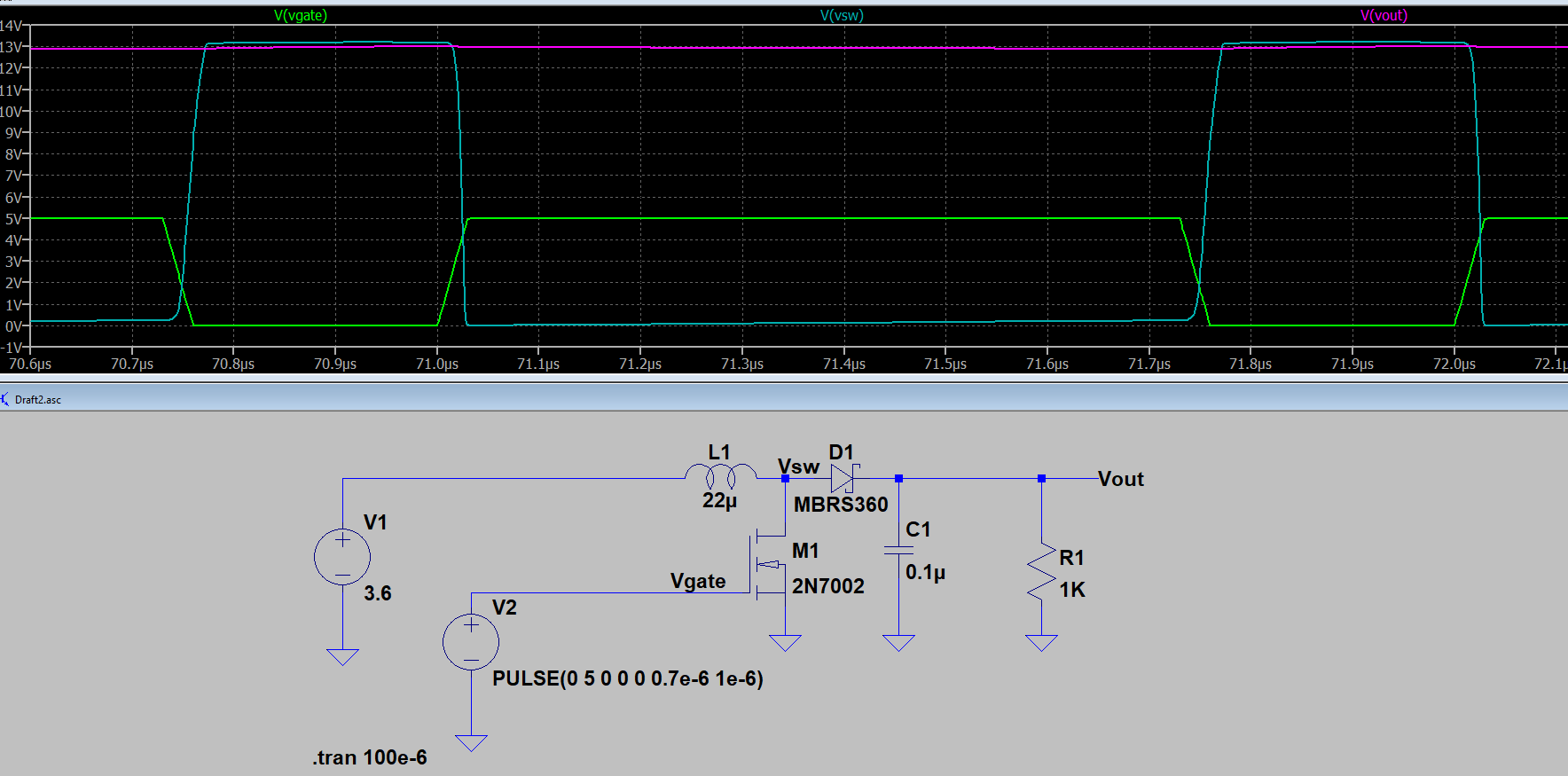 Essential Boost Converter Circuit
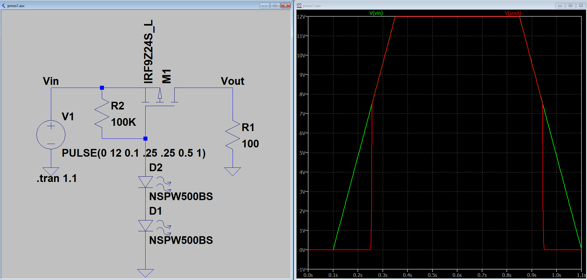 Low-Voltage Shutoff Circuit
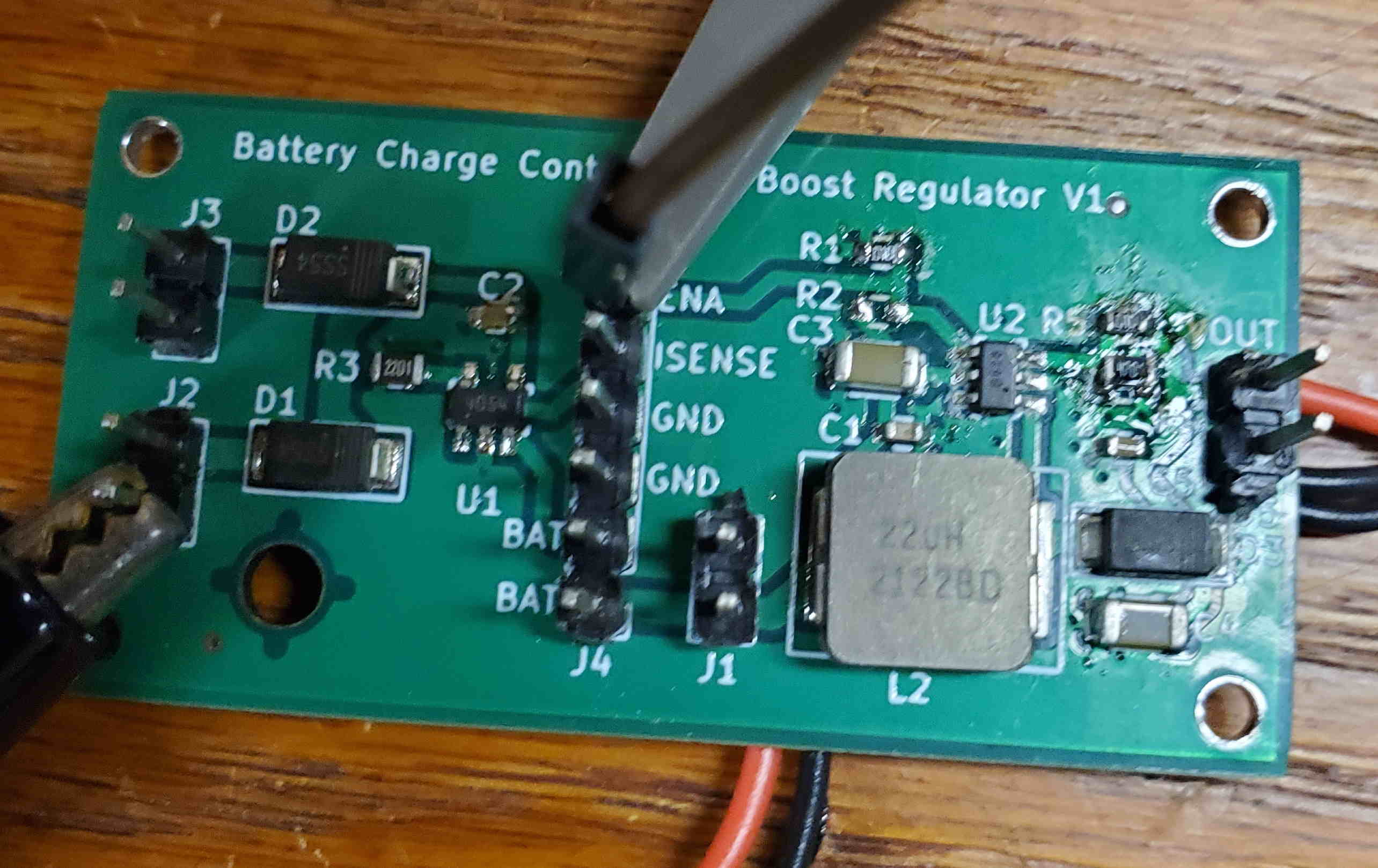
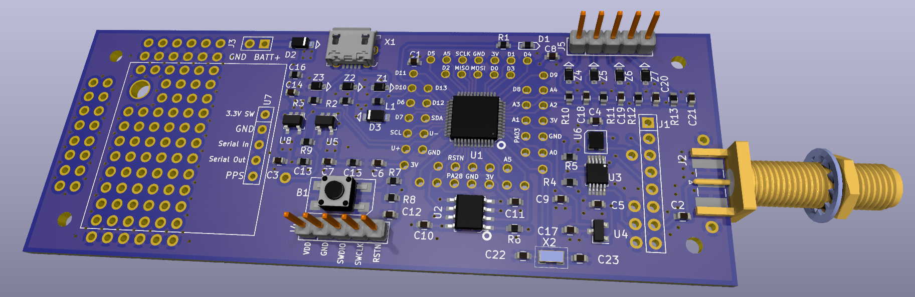 The Buoy Controller
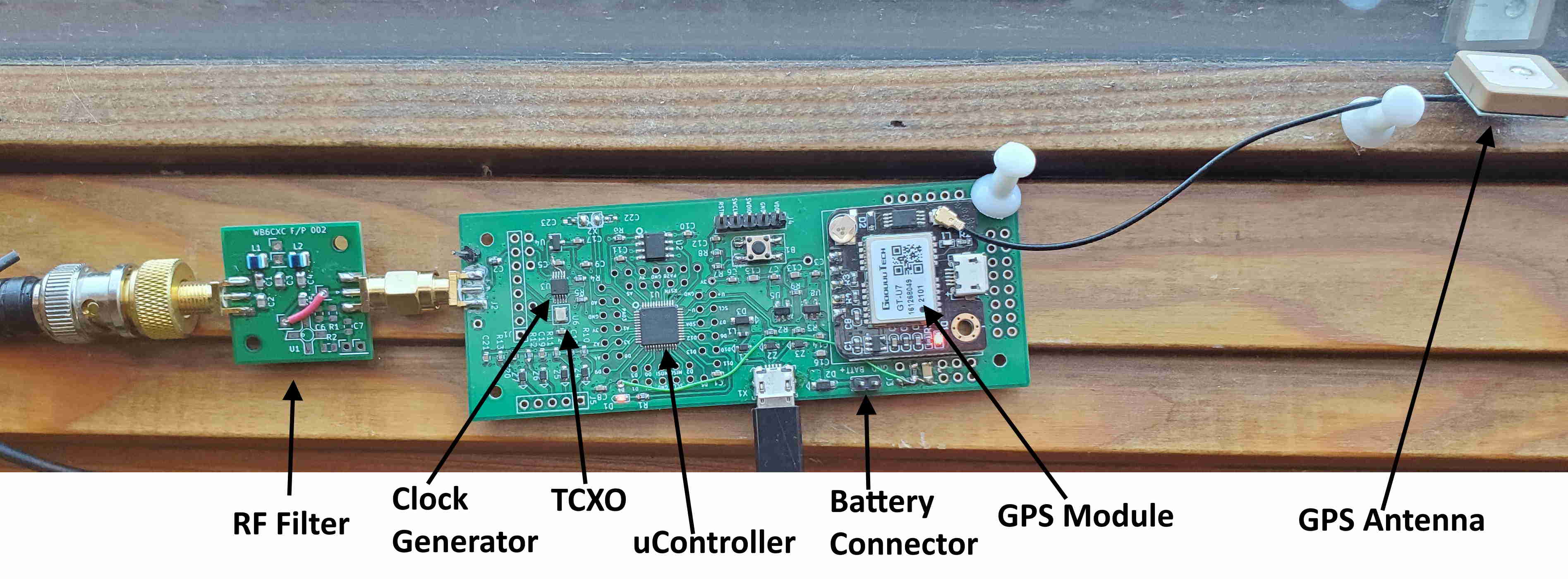 Buoy Controller Under Test
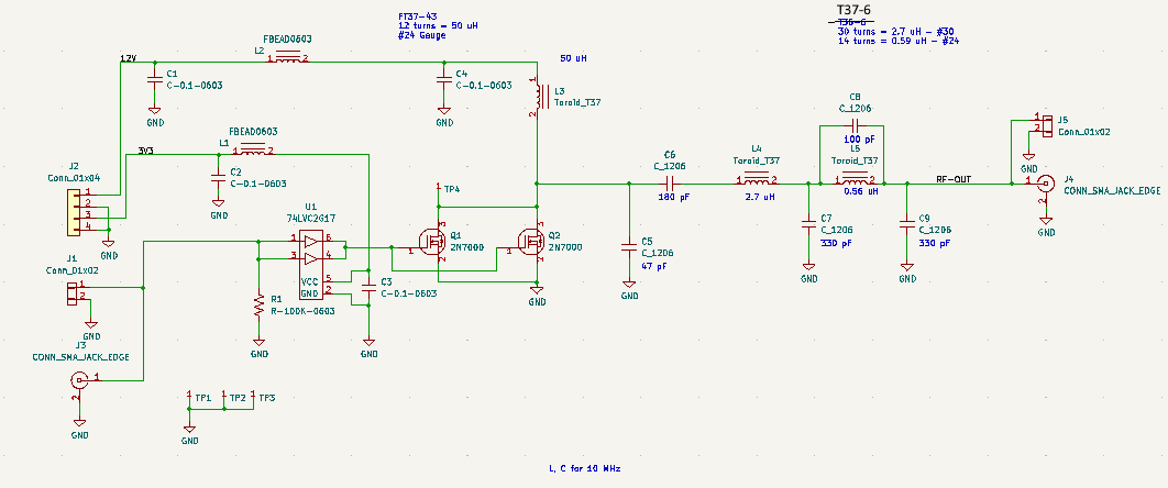
 Power Amplifier
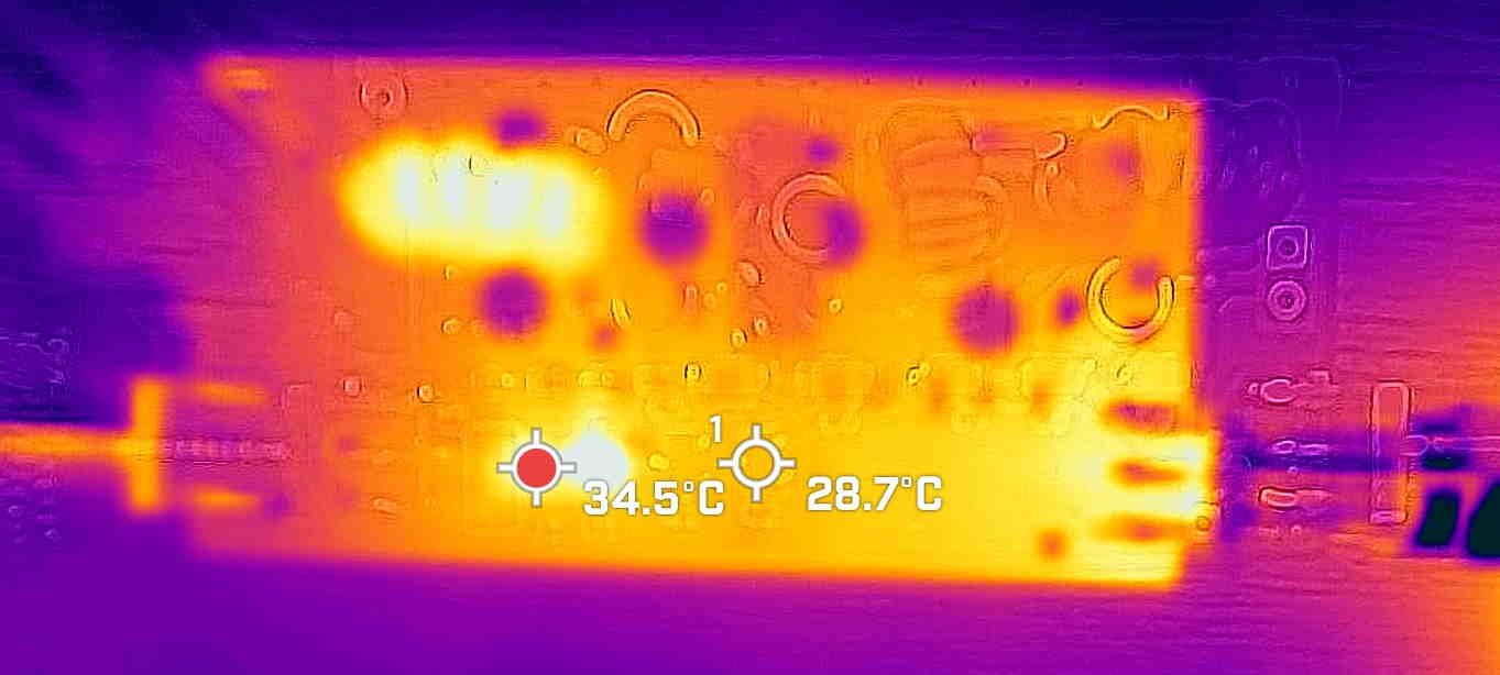
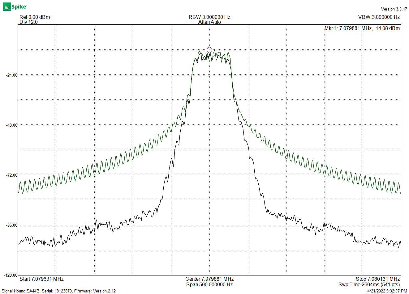
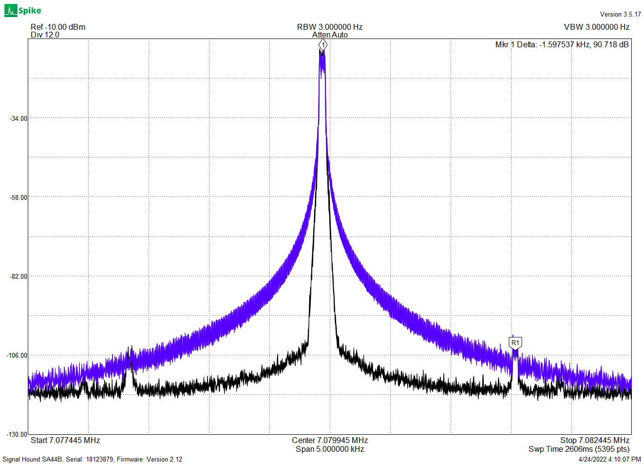
 Power Amplifier Output Spectrum (with 30dB attenuator)